3 Phase Power Analyser / EN
21 09/30/16 Version No. 00
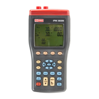
1. Press
key to turn on the instrument.
2. Press “WIRING” key to select the 1P3W electrical system test, the “1P3W” symbol will be
displayed.
3. Connect the voltage test leads and current probes to the instrument :
Connect the black voltage test lead to the “N” terminal.
Connect the red voltage test lead to the “U1” terminal.
Connect the yellow voltage test lead to the “U2” terminal.
Connect the I1 current probe to the “I1” socket.
Connect the I2 current probe to the “I2” socket.
To measure ground leakage current, connect the I4 current probe output plug to the “I4”
socket.
4. Connect the voltage test leads and current probes to the electrical equipment to be tested as
shown in Figure 7. 1P3W Wiring Connection Diagram.
CAUTION:
Where possible, isolate the power to the electrical circuit to be tested before
connecting the voltage test leads and current probes
Connect the black voltage test alligator clip to the neutral conductor “N”.
Connect the red voltage test alligator clip to Phase 1 “L1”.
Connect the yellow voltage test alligator clip to Phase 2 “L2”.
Clamp the I1 current probe securely around Phase 1 “L1”.
11
Clamp the I2 current probe securely around Phase 2 “L2”.
12
To measure ground leakage current, clamp the I4 current probe securely around the ground
line “G”.
5. Press “POWER” key to select between Phase 1 (P1, Q1, S1, PF1), Phase 2 (P2, Q2, S2,
PF2) and total (Pt, Qt, St, PFt) measured values.
6. Frequency (Hz), Phase Angle (Θ), Ground Leakage Current (I4) and Power Factor (pF)
measurement:
Press “PFΘ” key to cycle shows the PF and Θ measured values.
Press “Hz I4” key to cycle shows the Hz and I4 measured values.
7. Voltage and Current THDR THDF measurement:
Please refer to section 4-1-12 “THD” key description.
8. Voltage and Current waveform harmonic measurement:
Please refer to section 4-1-25 “ MAG.” key description.
9. Power Maximum/Minimum measurement:
Please refer to section 4-1-10 “MAX” key description.
10. Energy measurement:
Press “ENERGY” key, the “Pt”, “Qt”, “St” and “PFt” or “φ
t” symbol are displayed and the
starting time of the energy measurement is displayed in the “STAR” line. The energy values
and the current time will be displayed during the energy measurement.