3 Phase Power Analyser / EN
09/30/16 Version No. 00 20
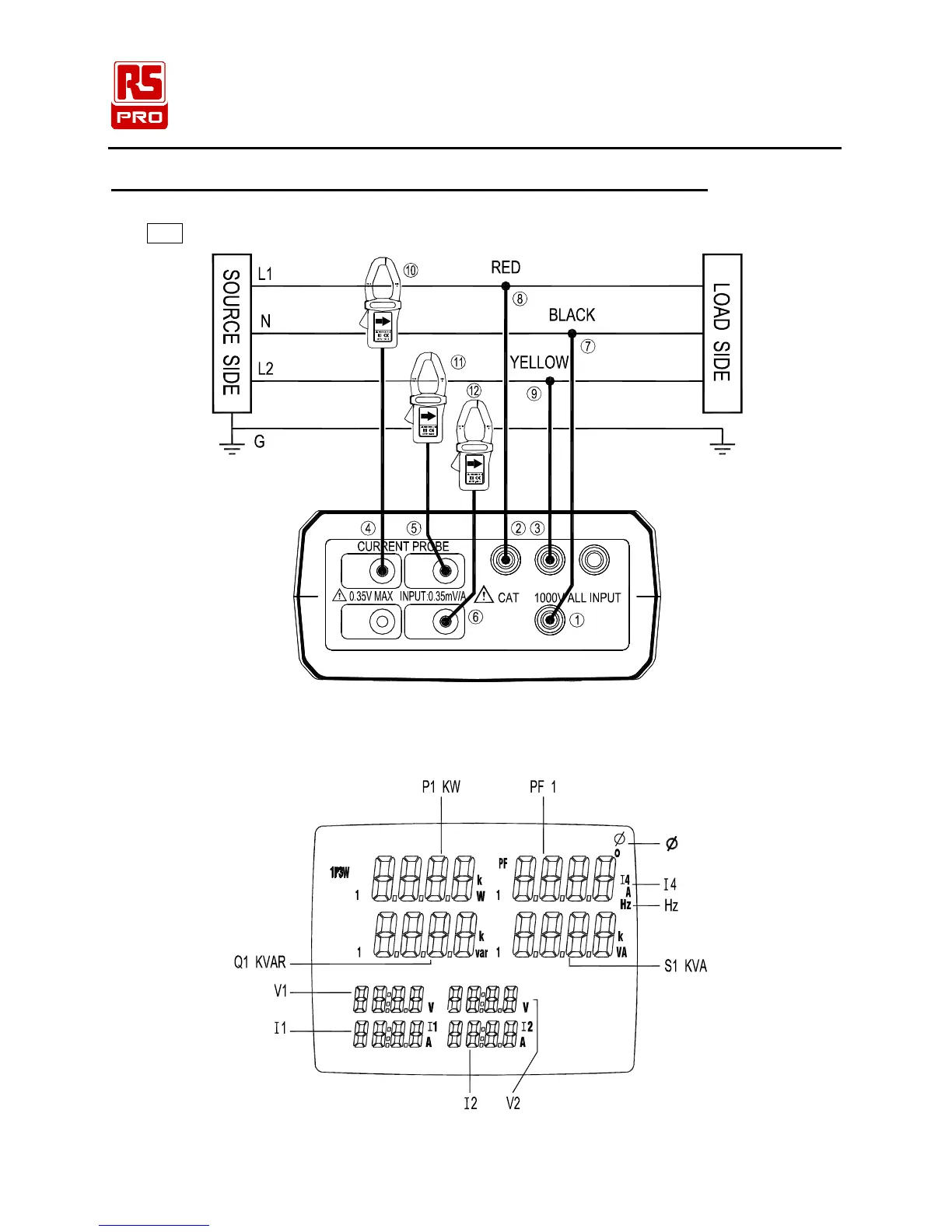
5-3 Single-Phase 3-Wire (1P3W) Power System Measurement
L1, L2 : Phase 1, Phase 2, N : Neutral, G : Ground
Face the current probe arrows toward the load
I3 I4
I1 I2
N
U2U1
Ⅲ
U3
Figure 7. 1P3W Wiring Connection Diagram
Note: U1 must be connected to the voltage source during the measurement of U2, I1 and I2,
because U1 is the main signal source of the whole instrument measuring system.
P
U1
Q
U2
S
Figure 8. 1P3W General Display