3 Phase Power Analyser / EN
09/30/16 Version No. 00 32
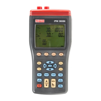
1. Press
key to turn on the instrument.
2. Press “WIRING” key to select the 3P4W electrical system test, the “3P4W” symbol will be
displayed.
3. Connect the voltage test leads to the instrument:
Connect the red voltage test lead to the “U1” terminal.
Connect the yellow voltage test lead to the “U2” terminal.
Connect the blue voltage test lead to the “U3” terminal.
Connect the black voltage test lead to the “N” terminal.
4. Connect the voltage test leads to the electrical equipment to be tested as shown in Figure 14.
3P4W Phase Sequence Connection Diagram
CAUTION:
Where possible, isolate the power to the electrical circuit to be tested before
connecting the voltage test leads and current probes
Connect the red voltage test alligator clip to Phase 1 “L1”.
Connect the yellow voltage test alligator clip to Phase 2 “L2”.
Connect the blue voltage test alligator clip to Phase 3 “L3”.
Connect the black voltage test lead to the “N” terminal.
Note. U1, U2 and U3 measured voltage must be greater than 30V, for rotary field detection
5. Press and hold down the “ ” key.
If the equipment under test is connected to the phases correctly, the clockwise rotation symbol
“ ”
is displayed.
If the phases are reversed, the counter clockwise symbol “ ”
is displayed.
Release the “ ” key to exit this measurement.