VW2106 Vibrating Wire Readout Manual
3.2 SINGLE FIELD INSTRUMENT CONNECTION – OLDER MODELS
The following instructions outline the steps to connect single field instruments:
1. Using hands or a screwdriver, lift the gates on the terminal strip.
2. Insert the stripped ends of the instrument cable to the matching wire transducer.
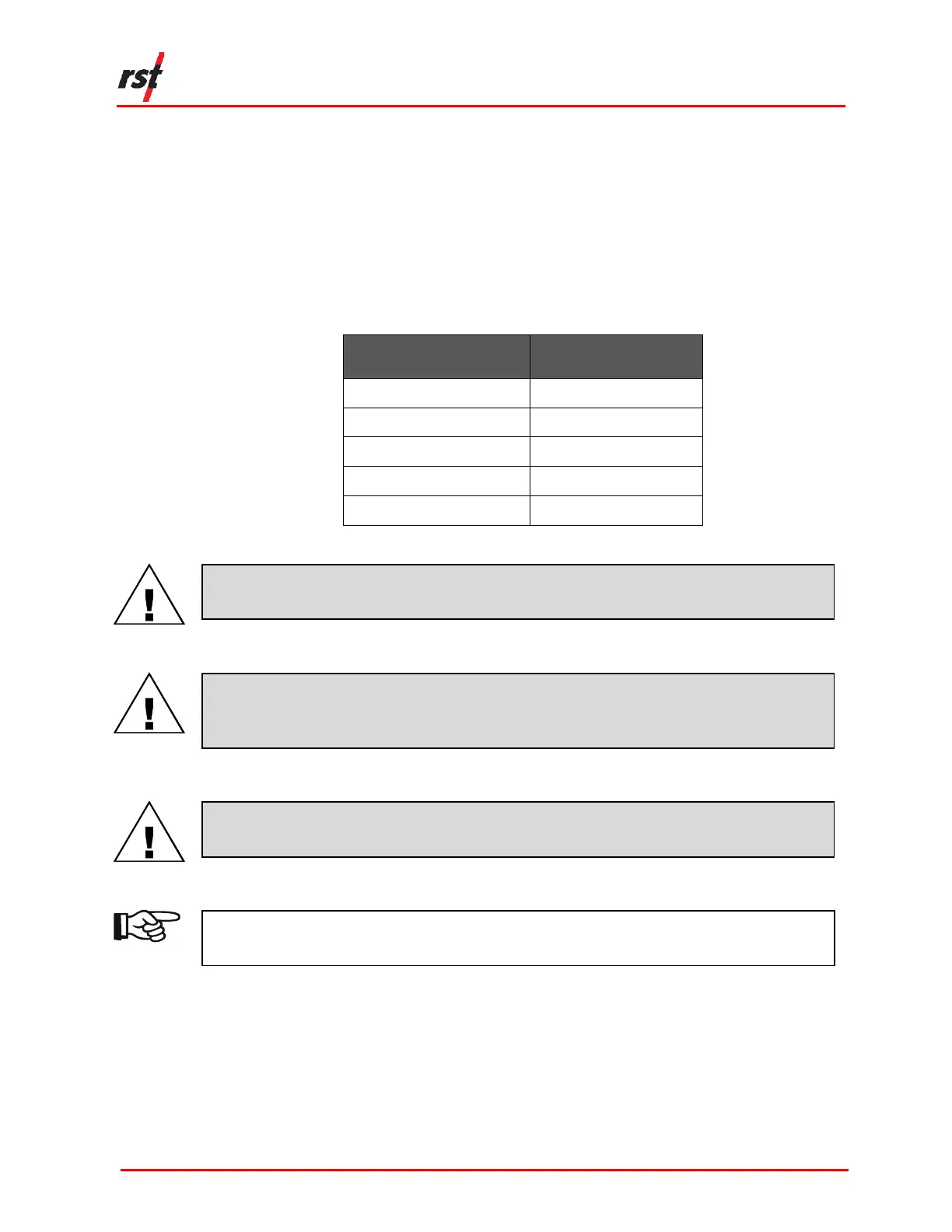
Refer to Table 3-2 for matching colours and wire transducers.
TABLE 3-2 STANDARD WIRING COLOUR CODES
CAUTION: MAKE SURE THAT THE WIRES ARE CLEAN AND FREE OF DIRT BEFORE
INSERTING THEM INTO THE TERMINALS.
CAUTION: ENSURE THAT THE TERMINALS ARE FREE FROM DIRT AND DEBRIS
BEFORE INSERTING THE WIRES. TERMINALS CAN BE BLOWN OUT WITH COMPRESSED
AIR IF NECESSARY.
3. Close each gate to secure the wire.
CAUTION: ENSURE THAT THE GATES ARE SECURED BEFORE CLOSING THE LID TO
THE UNIT TO AVOID DAMAGING THE GATES.
NOTE: APPLYING SOLDER TO THE BARE ENDS OF THE CABLE REDUCES FRAYING
OVER TIME. ALL RST SENSORS ARE PRE-TINNED IN THE FACTORY.
3.3 MULTI-CHANNEL CONNECTION
The VW 2106 may be connected to multi-channel instruments through its expansion
connection (Figure 1-1, 9).
Mating halves of the connectors are available through RST if your current sensors
are not equipped with the appropriate connector.

 Loading...