LIST OF FIGURES
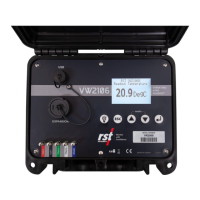
Figure 1-1 VW 2106 Readout ...................................................................................................... 1
Figure 1-2 Visual instructions for terminal posts and battery changes ........................................ 2
Figure 2-1 Power Off screen ...................................................................................................... 3
Figure 2-2 Auto Off screen ......................................................................................................... 3
Figure 2-3 Auto Power Off time .................................................................................................. 3
Figure 2-4 Auto Backlight Off ..................................................................................................... 4
Figure 2-5 Speaker On time ....................................................................................................... 4
Figure 3-1 Terminal posts .......................................................................................................... 5
Figure 3-2 Press down on the terminal post ............................................................................... 6
Figure 3-3 Correct angle for wire insertion ................................................................................. 6
Figure 3-4 Slide the wire into the gap ......................................................................................... 7
Figure 3-5 All wires connected to terminal posts ........................................................................ 7
Figure 3-6 Set time screen ......................................................................................................... 9
Figure 3-7 Memory screen ....................................................................................................... 10
Figure 3-8 Create location screen ............................................................................................ 10
Figure 3-9 Selecting the sweep frequency ............................................................................... 11
Figure 3-10 Thermistor type ..................................................................................................... 11
Figure 3-11 One sensor connected .......................................................................................... 12
Figure 4-1 VW2106 Readout details ........................................................................................ 13
Figure 4-2 Readings screen ..................................................................................................... 14
Figure 4-3 Storing a reading ..................................................................................................... 14
Figure 4-4 Storing a reading with 6 sensors ............................................................................. 15
Figure 4-5 Data logging interval ............................................................................................... 16
Figure 4-6 Data logging number ............................................................................................... 16
Figure 4-7 Logging screen ....................................................................................................... 17
Figure 4-8 Zeroing options ....................................................................................................... 17
Figure 4-9 Delete options ......................................................................................................... 18
Figure 5-1 Battery compartment ............................................................................................... 20
Figure 5-2 Battery installation ................................................................................................... 20
Figure 5-3 Battery voltage screen ............................................................................................ 21
LIST OF TABLES
Table 4-1 Standard Wiring Colour Codes ................................................................................... 5
Table 4-2 Standard Wiring Colour Codes ................................................................................... 8
Table 3-3 Sweep Frequencies ................................................................................................. 12