Chapter 1
Introduction
RUGGEDCOM RSG2488
Installation Guide
2 Configuration Ports and Indicator LEDs
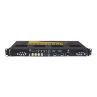
Figure 1: Front Panel
1. Power Module Indicator LEDs 2. RS232 Serial Console Port 3. Management Port 4. Alarm Indicator LED 5. MicroSD Port
6. Port Status Indicator LEDs
RS232 Serial Console Port This port is for interfacing directly with the device and access initial management functions.
Management Port This 10/100Base-T Ethernet port is used for system management that is out-of-band from
the switch fabric.
Alarm Indicator LED The alarm indicator LED illuminates when an alarm condition exists.
Power Module Indicator LEDs These LEDs indicate the status of the power modules. The top LED indicates the power
supply is supplying power. The bottom LED indicates the power supply is receiving power.
Port Status Indicator LEDs These LEDs indicate when ports are active.
MicroSD Port This port houses the microSD card containing the firmware and configuration for the device.
 Loading...