Product Overview
1.4.1 Fiber Optic Transceiver Orientation and Connection
Depending on the order code of the product, the RSG2000 series products can be
equipped with several different types of fiber optic ports. The Transmit (TX) and Receive
(RX) connections of each port must be properly connected and matched for proper link
and operation. Modules populated on the top row of the device typically have locking
mechanisms or tabs towards the top of the unit. Modules located on the bottom row of
the device have locking mechanisms or tabs towards the bottom of the device.
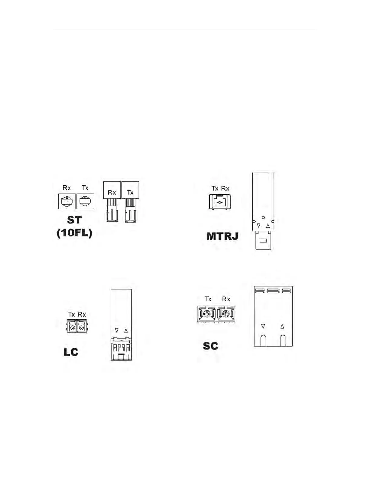
The drawings in the following figures show each fiber optic connector style with a side
and top view to allow the user to identify the proper cable connection orientation. If
modules are populated on the bottom row of the device, the transceiver orientation will
be reversed (ie RX and TX will be reversed).
Figure 4: 10FL ST connector
Figure 5: 100FX MTRJ connector
Figure 6: 100FX / 1000LX LC connector
Figure 7: 100FX / 1000LX SC connector
RuggedCom
®
10 RuggedSwitch
®
RSG2100