Product Overview
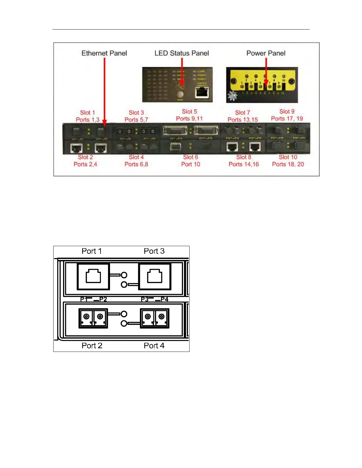
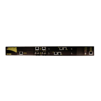
Figure 2: Ethernet, LED Status, and Power Panels
1.4 Ethernet Panel Description
Each Ethernet module is equipped with two LEDs that indicate link/activity status
information. The LED will be solid for ports with link, and will blink for activity. The
diagram in Figure 3 highlights the port and the associated link/activity LED.
Figure 3: Ethernet panel LED description
RuggedSwitch
®
RSG2100 9 RuggedCom
®