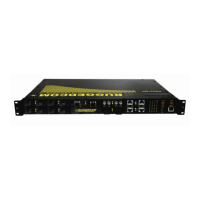
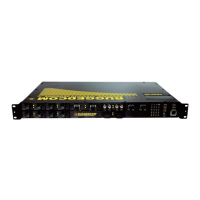
3.3 Display Panel Description
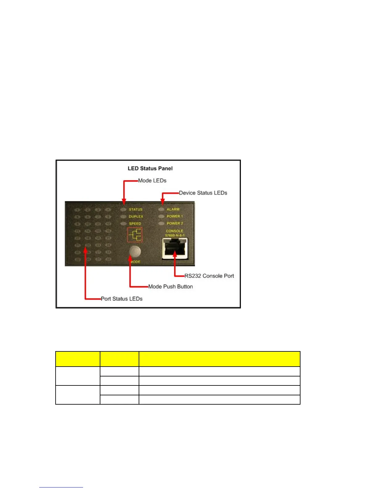
The RSG2000 series products are equipped with a versatile display panel, shown in Figure 1,
which is designed to provide quick status information for each port, as well as the entire device to
allow for simple diagnostics and troubleshooting. It features:
• RS232 console port for ‘out of band’ console access and configuration
• Power supply and Alarm status indicators
• Convenient port status indicators conveying Link-Activity, Duplex, or Speed via push-
button control.
• System reset via push-button if held for 5 seconds
Figure 1: RSG2000 Series LED Display Panel
Device status LEDs exist to provide a quick visual indicator to operators for operational status of
the unit. Table 1 defines the possible LED colours and the corresponding description.
LED Colour Description
Green Power supply operating normal
PS1 (Main) /
PS2 (PoE)
Red Power supply failure
Red Alarm exist – login to console to determine alarm code
Alarm
Off No alarms exist
Table 1: LED Display – Device status LED behavior definition
8
© 2008 RuggedCom Inc. All rights reserved Rev105
 Loading...