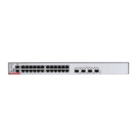
Hardware Installation and Reference Guide Preparing for Installation
56
Too high temperatures can accelerate the aging of insulation materials, greatly reducing the reliability of the switch and severely
affecting its service life.
Temperature and Humidity
0ºC to 45ºC (32ºF to 113ºF)
10% to 90% (non-condensing)
The ambient temperature and humidity of the switch are measured at the point that is 1.5 m (59.06 in.) above the floor and 0.4
m (15.75 in.) before the switch rack when there is no protective plate in front or at the back of the rack
2.2.3 Cleanliness Requirements
Dust poses a major threat to the switch. The indoor dust takes on a positive or negative static electric charge when falling on the switch,
causing poor contact of the metallic joint. Such electrostatic adhesion may occur more easily when the relative humidity is low, not
only affecting the service life of the switch, but also causing communication faults. The following table describes the requirements for
the dust content and granularity in the equipment room.
Dust particles (diameter ≥ 0.5 μm)
Dust particles (diameter ≥ 5 μm)
Apart from dust, the salt, acid, and sulfide in the air in the equipment room must meet strict requirements. These harmful substances
will accelerate metal corrosion and component aging. Therefore, the equipment room should be properly protected against the
intrusion of harmful gases, such as sulfur dioxide, hydrogen sulfide, nitrogen dioxide, and chlorine gas.
The Average refers to the average limit of harmful gas in one week. The Maximum value is the upper limit of the harmful gas
measured in one week for up to 30 minutes every day.
2.2.4 Anti-interference Requirements
The AP is susceptible to external interference by capacitive coupling, inductive coupling, electromagnetic waves, common impedance
(ground) coupling, or conduction over power lines, signal lines and output lines. Note that:
In a TN earthing system, use a 3-wire single-phase outlet that has a protective earth (PE) contact to allow the filter circuit in the
device to eliminate interference from the power grid.
The switch should be located far away from the large power radio launch pad, radar launch pad, and high-frequency large-current
devices.
Use EMI shielding such as shielded interface cables to minimize interference when necessary.
Route interface cables only indoors to prevent signal ports from getting damaged by overvoltage or overcurrent caused by
lightning strikes.
 Loading...


