EasyManua.ls Logo

Runxin F105AD - User Manual

Default Icon
51 pages
Print Icon
To Next Page IconTo Next Page
Loading...
Multi-functional Flow Control Valve for
Water Treatment Systems
82602EH (Old ModelF105AD)
82602FH (Old ModelF105BD)
82602ED (Old ModelF105AH)
82602FD (Old ModelF105BH)
86602ED (Old ModelF105AHW)
86602FD (Old ModelF105BHW)
82603FD (Old ModelF136BHW)
User Manual
Please read this manual in details before using the valve and keep it
properly in order to consult in the future.
0WRX.466.598
International Patent Public No.:
WO 2006/007772
China Patent No.: ZL02220153.X
US Patent No.: 7549446
India Patent No.: 232582
Russia Patent No.:2349819
South Korea Patent No.:10-0914137
Mexico Patent No.: 268581
Australia Patent No.: 2005263257
Philippine Patent No.: 1-2006-502553
Taiwan Patent No.:M287896
Question and Answer IconNeed help?

Do you have a question about the Runxin F105AD and is the answer not in the manual?

Overview

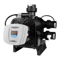
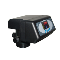
This document describes a multi-functional flow control valve for water treatment systems, specifically designed for softening or demineralization processes. It is suitable for residential softening systems, ion exchange equipment, and RO pretreatment softening systems.

Function Description

The valve offers a range of functions to optimize water treatment:

  • Softening/Demineralization: Primarily used for water softening or demineralization.
  • Regeneration Modes: Supports both down-flow and up-flow regeneration.
  • Brine Refill with Soft Water: Refills brine with soft water, enhancing regeneration efficiency. During brine refill and dissolve status, the system remains in service, allowing soft water to flow from the outlet, which saves regeneration time and improves working efficiency.
  • Brine Dry Mode: Protects the resin tank by preventing adverse reactions between the resin tank and salt.
  • Proportional Brine Draw: If the actual water consumption doesn't reach the set treatment capacity but the maximum interval regeneration days are met, brine is absorbed proportionally to the actual water consumption and water treatment capacity. This feature is designed to be more user-friendly and aims to save brine and water.
  • Leakage Protection: Can be equipped with an induction cotton or configured to close the valve inlet based on continuous water time or peak flow rate, thereby reducing losses from water leakage.
  • Salt Shortage Alarm: Allows input of salt adding quantity and resin volume. The system automatically calculates salt levels in the brine tank and displays "Check Remaining Salt" in the Service position if salt is low.
  • Vacation Mode: When activated, the valve inlet automatically closes to protect the resin in the resin tank.
  • Resin Maintenance/Replacement Prompt: Prompts "Call for check up resin" in the Service position when regeneration times reach a predefined number.
  • WIFI Control (WIFI version): Enables users to remotely check the valve status and control programs via a mobile APP.
  • Raw Water Mixing: An adjustable bolt allows mixing a portion of raw water with soft water to achieve desired hardness levels if the soft water is too soft.
  • Long Outage Indicator: If a power outage exceeds 3 days, the time of day indicator "12:12" flashes to remind users to reset the time. Other parameters do not require resetting.
  • Buttons Lock: Buttons on the controller lock after 1 minute of inactivity. Pressing the "up" and "down" buttons for 5 seconds unlocks them.
  • LCD Screen Display: Adopts an LCD display for clear and brief information.
  • Maximum Interval Regeneration Days: Prevents the system from entering regeneration prematurely if the service time reaches the setting days but the volume has not yet been consumed.
  • Adjustable Parameters: Parameters can be adjusted according to water quality and usage.

Important Technical Specifications

The valve operates under specific conditions:

  • Working Pressure: 0.15MPa – 0.6MPa
  • Water Temperature: 5°C – 50°C
  • Environment Temperature: 5°C – 50°C
  • Relative Humidity: ≤95% (25°C)
  • Electrical Facility: AC100 – 240V/50 – 60Hz
  • Water Turbidity: UP-flow regeneration <2FTU; Down-flow regeneration <5FTU
  • Water Hardness: First Grade Na⁺ <6.5mmol/L; Second Grade Na⁺ <10mmol/L
  • Free Chlorine: <0.1mg/L
  • Iron²⁺: <0.3mg/L
  • CODMn: <2mg/L (O₂)

Connector Size (Example for 82602ED):

  • Inlet/Outlet: G3/4"
  • Drain: NPT3/4"
  • Brine Line Connector: G3/8"
  • Base: 2.5"-8N PSM
  • Riser Pipe: 1.05"OD (Ø26.7)
  • Hard Water Bypass: No (82602ED, 82602FD); Yes (82603FD)
  • Regeneration Mode: Down-flow/up-flow

Main Technical Parameters:

  • Water Treatment Capacity: F105 (82602): 2m³/h; F136 (82603): 2.7m³/h (Measured under the condition of not installing bypass valve)
  • Transformer Input: AC100 – 240V/50 – 60Hz
  • Transformer Output: DC12V, 1.5A
  • Normal Work Cycle: Service → Brine Dissolve → Backwash → Brine & Slow Rinse → Fast Rinse.
  • Under Vacation Mode: Brine Refill → 240min. Brine Dissolve → Brine & Slow Rinse → Close.

Parameter Set (Factory Default):

  • Time of Day: Time of Day
  • Regeneration Time: 00:00
  • Hardness of Raw Water: 150 mg/L
  • Continuous Water Time: 00 min.
  • Peak Flow Rate for Close: 00 m³/h
  • Valve Model: F105/F136
  • Language: English
  • Flow Rate Unit:
  • Resin Volume: 08 L
  • Coefficient of W.T.C: 50K
  • Brine Draw Type: Up-flow
  • Backwash Time: 02 min.
  • Brine & Slow Rinse Time: 30 min.
  • Brine Refill Time: 03:00 min.:sec.
  • Fast Rinse Time: 3 min.
  • Interval Backwash Times: F-00
  • Interval Regeneration Days: 30 days
  • Regeneration Alarm Times: 300 times
  • Salt Adding Volume: 00 Kg

Usage Features

  • Installation: Requires professional installation. All materials and tools for installation should be obtained beforehand. The installation of product, pipes, and circuits must be accomplished by professionals.
  • Device Location: The filter or softener should be located close to the drain. Ensure adequate space for operation and maintenance. The brine tank needs to be close to the softener. Avoid placing the unit near heat sources, high humidity, corrosive environments, intense magnetic fields, or intense vibrations. Do not leave it outdoors.
  • Pipe Connections: Install the system where minimum loss in case of water leakage. Use PPR, corrugated, or UPVC pipes for installation; aluminum-plastic pipes should be avoided.
  • Riser Pipe Installation: Insert the riser pipe into the control valve and tighten. The riser pipe length should be within 2mm higher or 5mm lower than the tank top opening. Avoid filling floccules with resin to the resin tank. Ensure the O-ring inside the control valve does not fall out.
  • Flow Meter Installation: Insert the sealing ring into the internal thread of the inlet and outlet. Tighten the flow meter with the impeller to the water inlet of the valve. Insert the plug of the flow meter into the water inlet of the valve.
  • Bypass Valve Installation: Unplug clips from the bypass valve, remove connectors on inlet and outlet. Connect the bypass valve assembly into the connector on the inlet and outlet. Insert the flow meter sensor pin into the outlet with the impeller.
  • Leakage Sensors Installation: Insert the plug of the leakage sensor into the connector on the valve. Place the leakage sensor where it is most likely to contact water if leakage occurs.
  • Drain Pipeline Installation: Connect the DLFC into the drain outlet. Ensure the drain outlet is lower than the control valve and not longer than 3 meters. Do not connect drain with sewer directly. Avoid wastewater being absorbed into the water treatment equipment.
  • Brine Tube Connection: Connect the brine line flow control into the connector, then insert into the O-ring. Slide the G3/8 brine tube hose connector over the end of the brine tube. Put the filter net into the tube and insert the tube bushing into the end of the brine tube. Tighten the brine draw hose connector onto the valve connector, then insert the connector into the brine line connector, and clip it. Connect the other end of the brine tube with the brine tank. The liquid level controller and air-blocker should be installed in the brine tank.
  • Parameter Setting: Parameters like Time of Day, Regeneration Time, Water Hardness, Continuous Water Time, and Peak Flow Rate for Close can be set through the display panel.
  • Process Display: The display shows different statuses like In-Service, Brine Refilling, Backwashing, Brine & Slow Rinse, Fast Rinsing, Motor Running, and Error.
  • Leakage Protection Release: In normal operation, press and hold the "down" button for 5 seconds to exit leakage protection and enter service status. In vacation mode, press and hold the "down" button for 5 seconds to exit leakage protection and enter fast rinse status.

Maintenance Features

  • Professional Consultation: Consult professional installation or repairing personnel for normal operation.
  • Water Quality Monitoring: Test water periodically to verify system performance.
  • Resin Check: If water treatment capacity is low, check the resin. Add resin if short; replace if reddish brown or broken.
  • Salt Usage: Use only crystalline coarse salt (at least 99.5% pure) in the brine tank. Ensure there is always solid salt in the tank.
  • Pressure Management: Install a pressure reducing valve if water pressure exceeds 0.6MPa; install a booster pump if pressure is under 0.15MPa.
  • Troubleshooting Guide: The manual provides a comprehensive troubleshooting section covering common issues like softener failure to regenerate, WIFI function failure, regeneration time incorrect, softener supplies hard water, softener fails to draw brine, unit used too much salt, excessive water in brine tank, pressure lost or rusted, resin discharged through pipe, control valve cycle continuously, drain flows continuously, interrupted or irregular brine, water flows out from drain or brine pipe after regeneration, salt water in outlet pipe, water capacity decreases, and controller faults. Each problem has a corresponding cause and correction.
  • Parts List: Detailed construction figures and part numbers are provided for various components, including the valve body, meter type bypass valve, flow meter connector, and animated connector, facilitating easy identification and replacement of parts.
  • Warranty Card: A warranty card is included, valid for one year, covering manufacturing defects. It specifies procedures for repair and replacement, and contact information for the manufacturer.

Runxin F105AD Specifications

General IconGeneral
BrandRunxin
ModelF105AD
CategoryControl Unit
LanguageEnglish

Related product manuals