Axio Lab.A1 Contents / List of Illustrations Carl Zeiss
04/2013 430037-7144-001 5
LIST OF ILLUSTRATIONS
Fig. 1-1 "RADIATION" and "LED APERTURE" warning labels on Axio Lab.A1 for transmitted
and reflected light fluorescence ........................................................................................ 10
Fig. 1-2 "Hot surface below" warning label on Axio Lab.A1 for reflected light ................................ 11
Fig. 2-1 Axio Lab.A1, stand transmitted light ................................................................................. 27
Fig. 2-2 Axio Lab.A1, stand transmitted light polarization ............................................................... 29
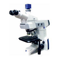
Fig. 2-3 Axio Lab.A1, stand transmitted and reflected light fluorescence ......................................... 31
Fig. 2-4 Axio Lab.A1, stand reflected light...................................................................................... 33
Fig. 2-5 Axio Lab.A1, stand transmitted light conoscopy................................................................. 35
Fig. 2-6 Axio Lab.A1 ergonomic stand with TÜV certificate "Ergonomically tested"......................... 36
Fig. 2-7 Binocular photo tube 30°/20 with fixed graduation 50:50 .................................................. 37
Fig. 2-8 Binocular photo tube 30°/23 with toggle graduation 100:0/0:100 ..................................... 37
Fig. 2-9 Setting the viewing height on the binocular tube ............................................................... 38
Fig. 2-10 Binocular ergo photo tube 8-38°/20 with fixed graduation 50:50 ....................................... 38
Fig. 2-11 Binocular ergo tube 8-33°/20 with vertical adjustment 50 mm ........................................... 39
Fig. 2-12 Binocular ergo photo tube 20°/23 with vertical adjustment ................................................ 40
Fig. 2-13 Binocular ergo photo tube 15°/23, telescopic with vertical adjustment ............................... 40
Fig. 2-14 Mechanical stage 75x30 R with specimen holder ............................................................... 41
Fig. 2-15 Mechanical stage 75x30 R ergonomic with stationary drive ................................................ 41
Fig. 2-16 Mechanical stage reflected light 75x30 R with specimen holding plate ............................... 41
Fig. 2-17 Rotary stage Pol
................................................................................................................ 42
Fig. 2-18 Filter mount on luminous-field diaphragm operating ring for filter d=32x4 mm .................. 42
Fig. 2-19 Condenser 0.9/1.25 H, D, Ph1, Ph2, Ph3 with modulator disk ............................................ 43
Fig. 2-20 Condenser 0.9/1.25 H ...................................................................................................... 43
Fig. 2-21 Overview fixture ............................................................................................................... 44
Fig. 2-22 Polarizers.......................................................................................................................... 44
Fig. 2-23 4-position reflector turret .................................................................................................. 45
Fig. 2-24 Nosepiece of the transmitted light polarization stand with mount for compensators ........... 45
Fig. 3-1 Setting up the microscope ................................................................................................ 46
Fig.
3-2 Placing tools in the storage compartment .......................................................................... 46
Fig. 3-3 Stowing power cord in cover flap for shipping ................................................................... 47
Fig. 3-4 Mounting the base plate ................................................................................................... 47
Fig. 3-5 Attaching the binocular tube ............................................................................................ 48
Fig. 3-6 Installing the eyepieces ..................................................................................................... 49
Fig. 3-7 Installing the eyepiece reticle ............................................................................................. 49
Fig. 3-8 Screwing in objectives....................................................................................................... 50
Fig. 3-9 Replacing the reflector module ......................................................................................... 51
Fig. 3-10 Replacing a mechanical stage ............................................................................................ 52
Fig. 3-11 Setting friction torque....................................................................................................... 53
Fig. 3-12 Replacing snap-in rotary stage Pol, detachable specimen guide Pol and stage clips ............. 54
Fig. 3-13 Centring rotary stage Pol .................................................................................................. 55
Fig. 3-14 Centering objectives ......................................................................................................... 56
Fig. 3-15 Attaching condenser ........................................................................................................ 57
Fig. 3-16 Removing the cover .......................................................................................................... 58
Fig. 3-17 Removing the LED lamp .................................................................................................... 58