START-UP
Axio Lab.A1 Installing standard components Carl Zeiss
04/2013 430037-7144-001 53
3.1.7.4 Setting friction torque of drive
knobs for X/Y adjustment of the
mechanical stage
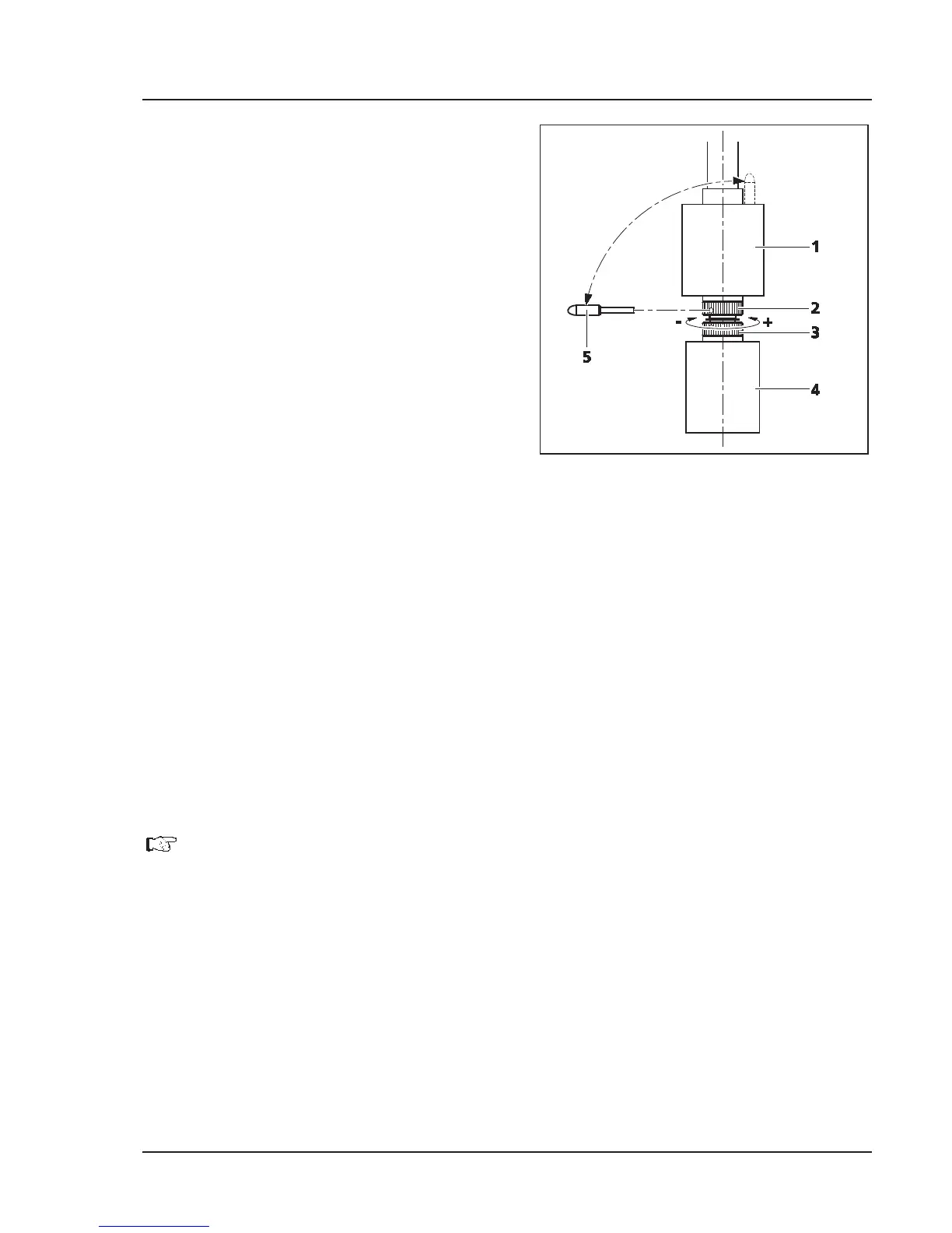
(1) X drive
x Push drive knob for X adjustment (Fig. 3-11/4)
right to the bottom.
x Remove supplied adjusting pin (Fig. 3-11/5)
from the drive knob for Y adjustment
(Fig. 3-11/1) and insert into one of the holes of
the lower hole nut(Fig. 3-11/3).
x Hold the drive knob for X adjustment
(Fig. 3-11/4) and turn the hole nut with the
adjusting pin in a clockwise direction (small
friction torque: –) or counter-clockwise (large
friction torque: +) until the desired freedom of
movement has been achieved (see Fig. 3-11).
x It should not be shifted more than one
revolution.
(2) Y drive
x Push drive knob for Y adjustment (Fig. 3-11/1) right to the top.
x Insert the supplied adjusting pin (Fig. 3-11/5) into the hole of the upper hole nut (Fig. 3-11/2).
x Hold the drive knob for Y adjustment (Fig. 3-11/1) and turn the hole nut with the adjusting pin in a
clockwise direction (small friction torque: –) or counter-clockwise (large friction torque: +) until the
desired freedom of movement has been achieved.
x It should not be shifted more than one revolution.
x Re-insert the adjusting pin into the drive knob for Y adjustment (Fig. 3-11/1).
Set the friction torque on the mechanical stage with ergonomic, stationary X-
Y drive
analogously. No tool is required for the purpose. The lock-nut (silver) of the respective drive
can be adjusted manually; hold the drive knob tight.
Fig. 3-11 Setting friction torque