START-UP
Carl Zeiss Installing standard components Axio Lab.A1
52 430037-7144-001 04/2013
3.1.7 Mounting a mechanical stage
Axio Lab.A1 stands are fitted with the respective
mechanical stage at the factory according to
customer requirements.
The friction torque of the drive knobs is set at an
average value at the factory.
Should the stage need to be replaced or the stage
settings changed, proceed as follows:
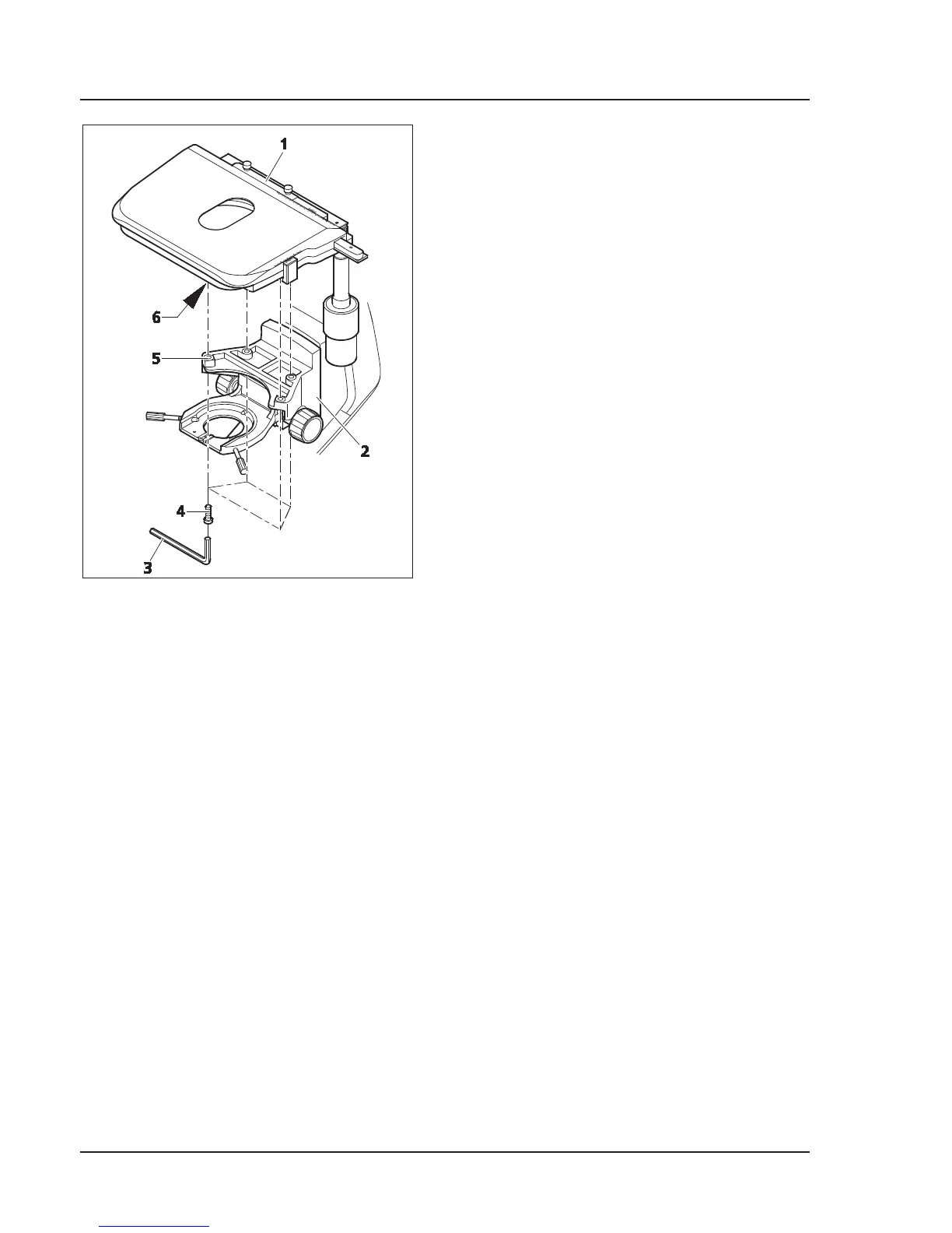
3.1.7.1 Dismantling a stage
x Remove the four fastening screws (Fig. 3-10/4)
on the stage carrier (Fig. 3-10/2) using an SW 3
(Fig. 3-10/3) Allen wrench.
x Remove stage (Fig. 3-10/1) upwards from the
stage carrier.
3.1.7.2 Installing the stage
x Place stage (Fig. 3-10/1) onto stage carrier (Fig. 3-10/2) in such a manner that the threaded holes on
the bottom of the stage (Fig. 3-10/6) are positioned above the stage carrier openings (Fig. 3-10/5).
x Insert four fastening screws (Fig. 3-10/4) through the stage carrier from below and screw them into
the bottom of the stage.
x Turn the stage to orient it in an XY direction and tighten the fastening screws.
3.1.7.3 Setting drive length on stage drive
The length of the X and Y drives can be changed by shifting the respective drive knob (Fig. 3-11/4 or 1)
axially within a range of approx. 15 mm.
Fig. 3-10 Replacing a mechanical stage