OPERATION
Axio Lab.A1 Lighting and contrasting method in transmitted light Carl Zeiss
04/2013 430037-7144-001 99
x Set the microscope as in the transmitted light
brightfield according to KÖHLER (see Section
4.1.1).
x Swivel polarizer (Fig. 4-12/3) into the light path
and, if it is rotatable, position it at 0°.
x Swivel the analyzer into the beam path and
bring into a crossed position with the setting
wheel. (The field of view will now appear dark)
x Place the specimen on the stage and focus on
it.
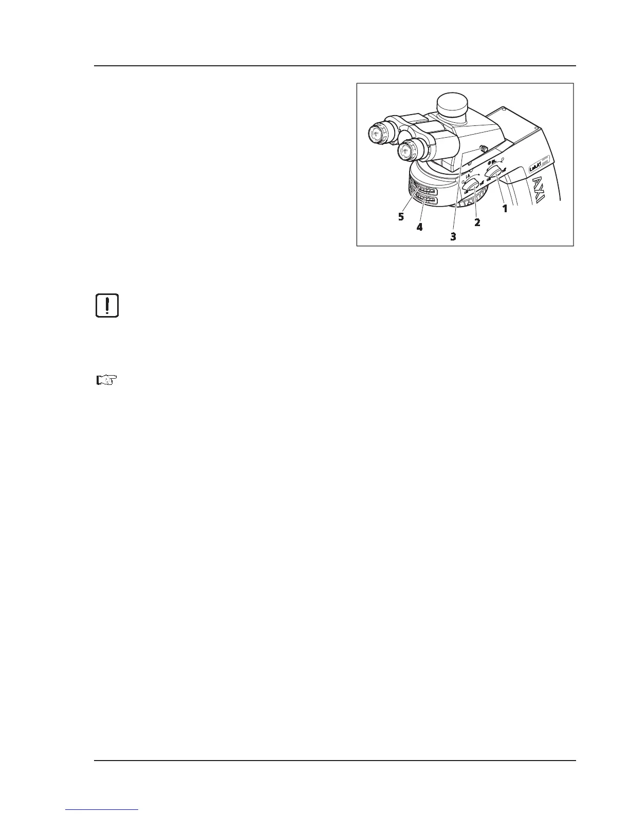
x Swivel the analyzer into the beam path (on
position) with rotary knob A (Fig. 4-17/2). The
direction of oscillation can be changed using
the setting wheel (Fig. 4-17/4) of the analyzer.
CAUTION
The movements of rotary knobs A and BL
and the respective setting wheels are coupled with
one another. Only one control element should therefore be operated at a time and the
movement of the other should not be inhibited or blocked. Mechanical damage may otherwise
occur.
If rotary knob BL is set at the on position, rotary knob A is automatically carried if it is not
already in the on position.
If, on the other hand, rotary knob A is set to the off position, if it is not already at the off
position rotary knob BL is automatically carried.
x Place a selected crystal in the center of the crossline reticle.
x Swivel in objective N-Achroplan 50x/0.8 Pol or EC Plan-Neofluar 40x/0.9 Pol and focus with the
focusing drive.
x If necessary, close the luminous-field aperture to avoid superimposition of the axial figure by axial
figures of neighboring crystals. The smallest crystal range that can be faded out is approx. 170 μm.
x Switch on Bertrand lens BL (Fig. 4-17/1) (Position on). The axial figure will appear in the field of view.
x Bring the axial figure into focus with setting wheel (Fig. 4-17/5).
4.1.7.2
Evaluation
Crystalline anisotropic specimens can be separated into optical uni- and biaxial, in each case with
"optically positive" or "negative" character.
Uniaxial crystals display a black cross when the optical axis is parallel to the direction of view.
Depending on the size of the birefringence and specimen thickness, concentrically arranged
colored interference rings (so-called isochromes) may appear (see also Fig. 4-11 second row).
This cross remains closed when the stage is rotated. Depending on the section it may lie within or outside
the displayed objective pupil.
Fig. 4-17 Axio Lab.A1 for transmitted light
conoscopy