EasyManua.ls Logo

SAB Goblin 700 User Manual

SAB Goblin 700
44 pages
To Next Page IconTo Next Page
Page #1 background imageLoading...
Page #1 background image
GOBLIN 700 KYLE STACY EDITION
SAB HELI DIVISIONSAB HELI DIVISION
- Carefully check your model before
each flight to ensure it is airworthy.
- Consider flying only in areas
dedicated to the use of
model helicopters.
- Check and inspect the flying
area to ensure it is clear of
people orbstacles.
- Rotor blades can rotate at very
high speeds! Be aware of the
danger they pose.
- Always keep the model at a
safe distance from other pilots
and spectators.
- Avoid maneuvers with trajectories
towards a crowd.
- Always maintain a safe distance
from the model.
Question and Answer IconNeed help?

Do you have a question about the SAB Goblin 700 and is the answer not in the manual?

SAB Goblin 700 Specifications

General IconGeneral
Tail blade length105 mm
Power SourceElectric
Skill LevelAdvanced
Cyclic servosStandard size
Battery12S LiPo
TypeHelicopter
Main blade length690mm
MaterialCarbon fiber and aluminum

Summary

Chapter 1, Serial Number

VERY IMPORTANT

Register your helicopter's serial number for updates and support.

SPECIFICATIONS

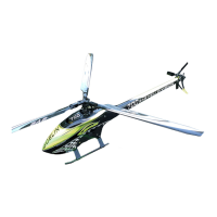
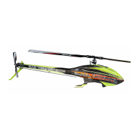
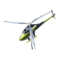
Technical details and dimensions of the helicopter.

Chapter 2, Important Notes

IMPORTANT NOTES

Critical safety information, warnings, and disclaimers about helicopter use.

SAFETY GUIDELINES

Rules for safe operation, including flying areas and precautions.

NOTES FOR ASSEMBLY

Guidance and symbols for the correct assembly process.

Chapter 3, Components and Box

ADDITIONAL COMPONENTS REQUIRED

List of external parts and electronics needed for the model.

TOOLS, LUBRICANTS, ADHESIVES

Necessary tools and materials for assembly.

Chapter 4, Carbon Frame

Chapter 5, Transmission Assembly

Chapter 6, Head

Radius Arm Assembly

Instructions for assembling the radius arm components.

Center Hub Assembly

Steps for assembling the central hub of the rotor head.

Swashplate Assembly

Guide for assembling the swashplate mechanism.

Main Blade Grip Assembly

Instructions for assembling the main blade grips.

Linkage Rod A Assembly

Details on assembling linkage rod A.

Chapter 7, Assembling The Modules

Chapter 8, Installation Of Swashplate Servos

INSTALLATION OF SWASHPLATE SERVOS

Guide for servo placement and linkage setup.

ASSEMBLY OF THE BALL ON THE HORN

How to attach balls to servo horns for alignment.

SERVO ASSEMBLY 1, 2, 3

Specifics for assembling servos to the frame.

Chapter 9, Installation Of The Motor

TRANSMISSION SETUP

Guidance on choosing motor reduction ratios for efficiency.

GOBLIN 700 KYLE STACY EDITION CONFIGURATIONS

Example configurations for motor, ESC, and pinion.

MOTOR BELT TENSION

Chapter 10, Installation Of The ESC

DE-BURR THE SIDE FRAMES

Advice on preparing carbon frames for wire routing.

ESC INSTALLATION

Steps for installing the electronic speed controller (ESC).

Chapter 11, Installation Of Flybarless Unit and RX

FLYBARLESS CONTROL UNIT AND RX INSTALLATION

Guide for installing FBL unit and receiver.

Chapter 12, Tail System

Tail Pitch Slider Assembly

Instructions for assembling the tail pitch slider.

Tail Blade Grip Assembly

Steps for assembling the tail blade grips.

Tail System Assembly

General assembly of the tail system components.

Bell Crank Lever Assembly

Tail Side Plate Assembly

Tail System Assembly

Tail Boom Assembly

Locking Element Tail Assembly

Tail Servo Installation

Tail Boom Assembly

TAIL BELT TENSION

CANOPY

Chapter 13, Installation Of The Boom

BOOM ASSEMBLY

Steps for assembling the tail boom.

TAIL BELT TENSION

CANOPY

Chapter 14, Battery

BATTERIES

Guide to attaching and positioning batteries for optimal balance.

Chapter 15, In Flight

SERIAL NUMBER

Location and registration of the serial number tag.

OPERATIONS BEFORE FLIGHT

Pre-flight checks, setup, and safety procedures.

IN FLIGHT

Tips for initial flights, break-in, and performance.

Chapter 16, Maintenance

ABOUT HPS3

Information on the HPS3 head system and its settings.

ABOUT HPS3 SETUP

Setup guidelines for the HPS3 head for optimal performance.

MAINTENANCE

Routine checks for wear, lubrication, and screw tightness.

Chapter 17, Exploded view, Carbon Frame

Chapter 17, Exploded view, Transmission Assembly

Chapter 17, Exploded view, Head System

Chapter 17, Exploded view, Tail System

Chapter 18, Spare Parts

Related product manuals