9
!
!
MX3+ v1.06 EN
© 2018 SafeLine and all the SafeLine products and accessories are copyrighted by law.
Installation
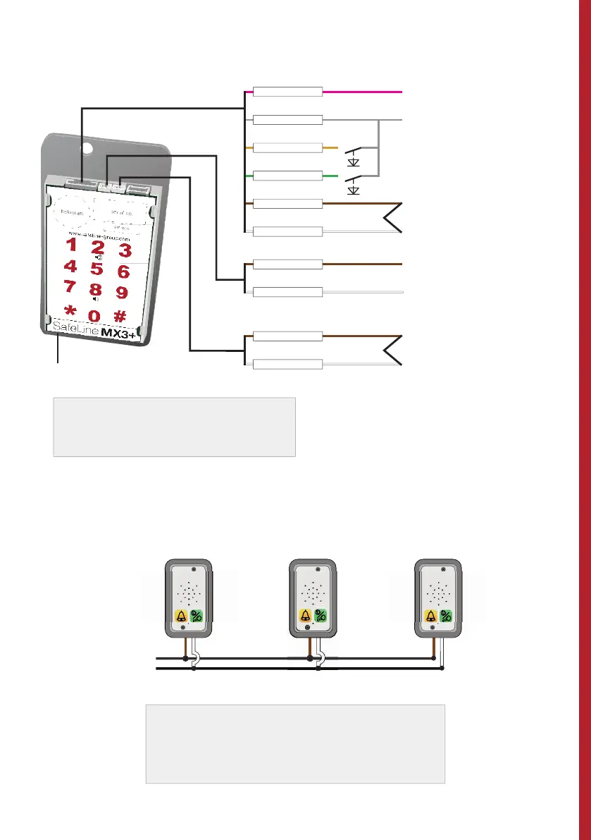
WIRING DIAGRAM
PINK
GREY
YELLOW
GREEN
BROWN
WHITE
Voltage supply +10 - 30 VDC
Voltage supply 0 VDC
Additional input (fi lter)
Input alarm button
Telephone line in
Output 1
Output 2
Additional alarm button, only N/O.
NOTE: *Cable13 is required.
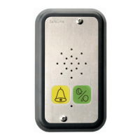
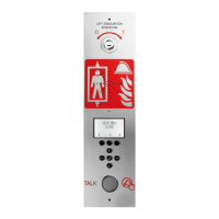
Additional Voice Unit
For example: LT-STAT01
BROWN
WHITE
BROWN
WHITE
Parallel-wiring, SafeLine MX3+ on PSTN Line (max 9 units)
Telephone line in
In order to access the unit remotely, it needs to
be assigned a unit number.
Please refere to the Parameter list (*82*) for
more information.
NOTE:
Please refer
to the Parameterlist
*88* for programming
information.
*Cable13 is required.
When connecting an additional remote
station *Cable14 is required.