VG5 Installation & Quick-Start Manual 23
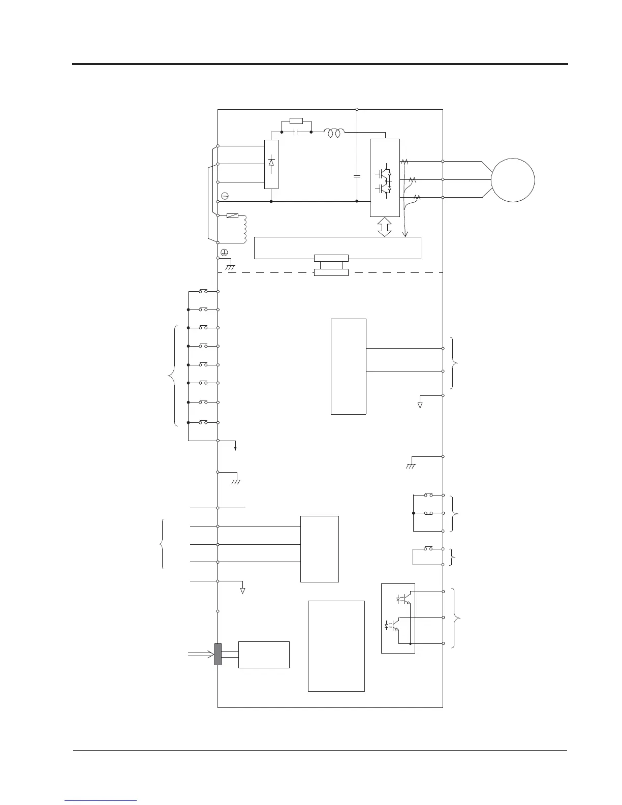
VG5 Standard Connection Diagram
Figure 11 VG5 Terminal Diagram - Model CIMR-VG5U5110
Digital
RS-232
Serial Port
Analog Inputs
(250)
Operator
(10-pin)
IM
1 - Forward Run when CLOSED
2 - Reverse Run when CLOSED
3
11 (Com)
4
5
6
15
13
14
17
PWM
Multi-Function
Inputs
12
(+15V, 20mA)
(20k)
(0V)
-10 to +10V
4 to 20mA
-10 to +10V 23
(Com) 22
12
18
19
20
9
10
Multi-Function
Analog Outputs
A/D
±11 bit
Gate Drive
T1
T2
T3
L1
L2
L3
7
8
16
(20k)
-10 to +10V
-10 to +10V 21
33
(-15V, 20mA)
26
27
Multi-Function
PHC Outputs
48V, 50mA or less
25
3
+
l
1
Fault Contact Outputs
250VAC, 1A or less
30VDC, 1A or less
Multi-Function
Contact Output
l
2
Chapter 1 - Receiving & Installation
Wiring