VG5 Installation & Quick-Start Manual 107
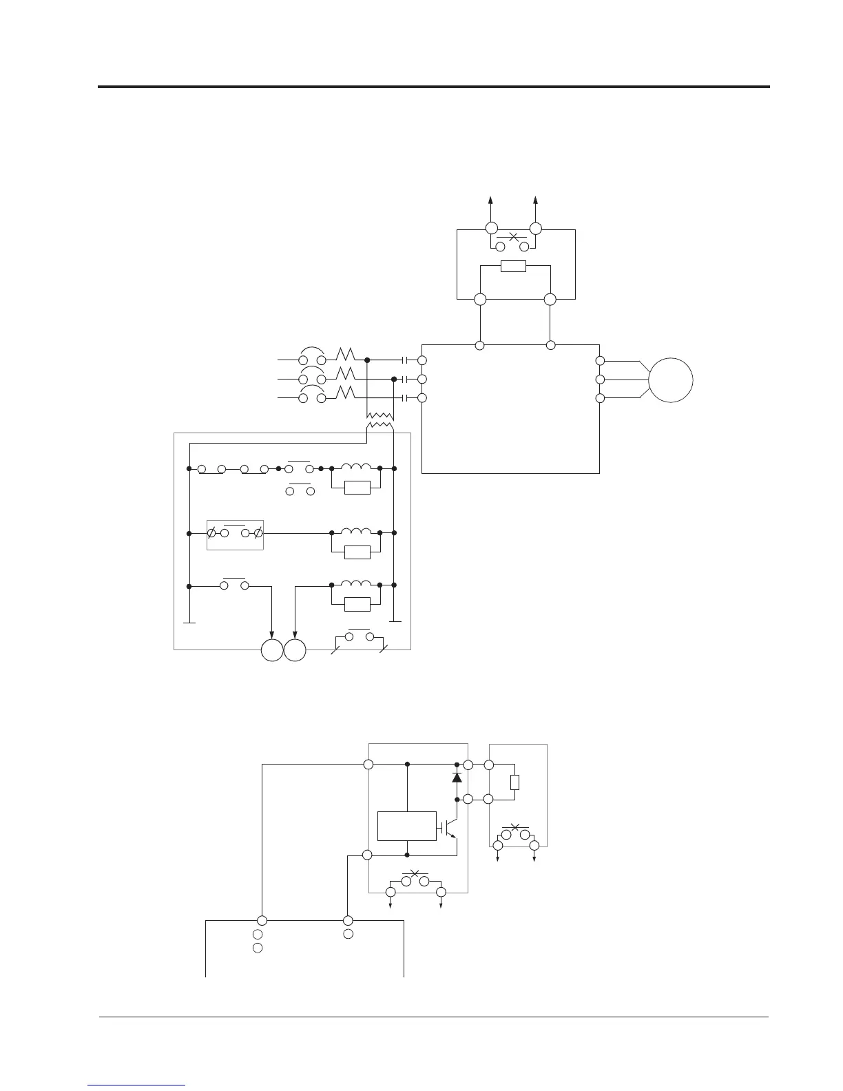
A.4 BRAKING CONNECTION DIAGRAMS ( CDBR Type)
Braking Resistor Unit
230V: VG5U20P4 to 27P5
460V: VG5U40P4 to 4015
P
B
1 2
Overload Relay Trip Contact
Braking Resistor Unit
Overload Relay Trip Contact
of Braking Resistor Unit
1 2
MC
Fault Contact
TRX
SA
TRX
THRX
SA
SA
MC
MC
THRX
ON
OFF
MA
MC
VS-616PC5
L1
L2
L3
T1
T2
T3
L1
L2
L3
MCCB
MC
B1
B2
M
Figure 24 External Control Circuit for VG5 Braking Resistor Connection
230V: VG5U2011 to 2075
Figure 25 External Control Circuit for VG5 Braking Unit Connection
Braking Unit
Braking Resistor
Level
P0
P
B
B
1
2
P
Unit
3
4
N
Detection
Overload Relay Trip Contact
-
+
3
3 & 4 output signal to
multi-function fault input.
460V: VG5U4018 to 4300
575V: VG5U51P5 to 5022
575V: VG5U5030 to 5160
+
(Use for G5U5030 to 5160)
1
Appendix
Braking Connection Diagrams