42 VG5 Installation & Quick-Start Manual
Operation by Control Circuit Terminal Signal
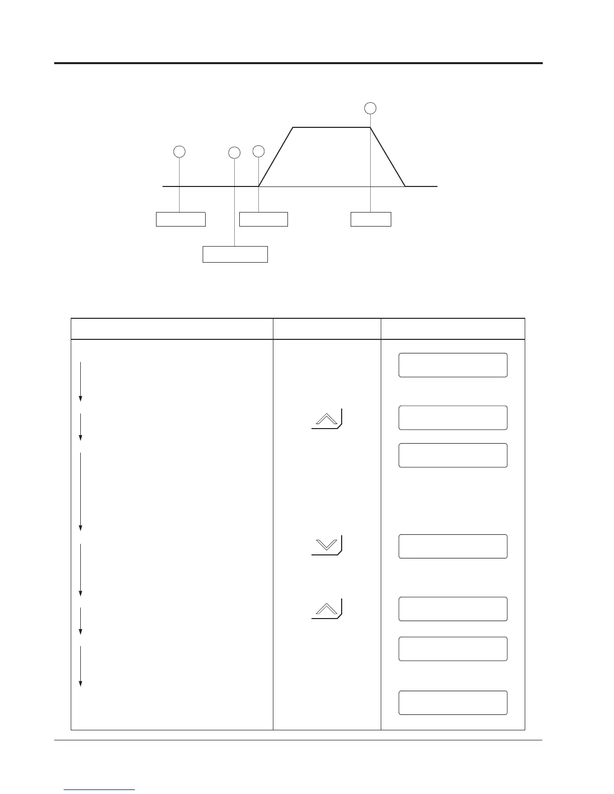
The diagram below shows a typical operation profile using the control circuit terminal signals.
Typical Operation Example by Control Circuit Terminal Signal
Description Key Sequence Digital Operator Display
Figure 16 Operation Sequence by Control Circuit Terminal Signal
Power ON
Frequency Setting
Operation
Forward
60Hz
Stop
1
2
3
4
cPower ON
·Displays frequency reference value.
REMOTE mode is preset at the factory.
Output Frequency Display
·Switch to output frequency display.
Forward Jog Run (6Hz)
·Close between control circuit terminals 1 &
11, and 7 & 11 closed to perform JOG run.
Run & FWD LEDs illuminate.
·Open between terminals 1 & 11, and 7 & 11
after verifying JOG operation
dFrequency Setting
·Input frequency reference via terminal 13
(voltage) or 14 (voltage/current) and verify
the input value with the digital operator.
Output Frequency Display
·Select output frequency monitor display.
eForward Run
·Close between terminals 1 & 11 to perform
forward run.
fStop
·Open between terminals 1 & 11 to stop
operation. Stop LED illuminates.
Frequency Ref
REMOTE LED (SEQ, REF) ON
U1-01 = 0.00 Hz
Output Freq
U1-02 = 0.00 Hz
Output Freq
U1-02 = 60.00 Hz
Output Freq
U1-02 = 0.00 Hz
Output Freq
U1-02 = 6.00 Hz
Frequency Ref
U1-01 = 60.00 Hz
Output Freq
U1-02 = 0.00 Hz
Chapter 2 - Operation
Trial Operation