34 VG5 Installation & Quick-Start Manual
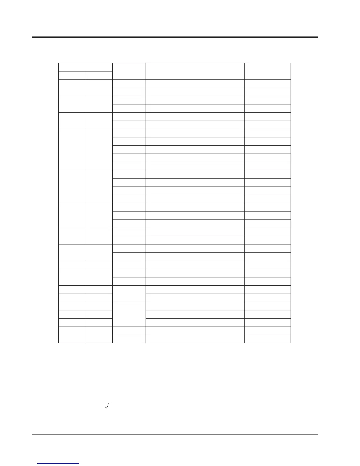
Wire and Terminal Screw Sizes (continued)
JST Closed Loop Connectors
Note 1:
The use of a JST closed-loop connector (lug) is recommended to maintain proper clearances. Please contact your Saftronics repre-
sentative for more information.
Note 2:
Voltage drop should be considered when determining wire size. Voltage drop can be calculated using the following equation:
Select a wire size so that voltage drop will be less than 2% of the normal rated voltage.
Wire Size *
Terminal
Screw
JST Closed-Loop Connectors (Lugs)
Max. Torque
lb-in (N·m)
AWG mm
2
20 0.5
M3.5 1.25 - 3.5 8.9 (1.0)
M4 1.25 - 4 12.4 (1.4)
18 0.75
M3.5 1.25 - 3.5 8.9 (1.0)
M4 1.25 - 4 12.4 (1.4)
16 1.25
M3.5 1.25 - 3.5 8.9 (1.0)
M4 1.25 - 4 12.4 (1.4)
14 2
M3.5 2 - 3.5 8.9 (1.0)
M4 2 - 4 12.4 (1.4)
M5 2 - 5 22.1 (2.5)
M6 2 - 6 45.1 (5.1)
M8 2 - 8 90.3 (10.2)
12 - 10 3.5 - 5.5
M4 5.5 - 4 12.4 (1.4)
M5 5.5 - 5 22.1 (2.5)
M6 5.5 - 6 45.1 (5.1)
M8 5.5 - 8 90.3 (10.2)
8 8
M5 8 - 5 22.1 (2.5)
M6 8 - 6 45.1 (5.1)
M8 8 - 8 90.3 (10.2)
6 14
M6 14 - 6 45.1 (5.1)
M8 14 - 8 90.3 (10.2)
4 22
M6 22 - 6 45.1 (5.1)
M8 22 - 8 90.3 (10.2)
3 - 2 30 - 38 M8 38 - 8 90.3 (10.2)
1 - 1/0 50 - 60
M8 60 - 8 90.3 (10.2)
M10 60 - 10 203.6 (23.0)
3/0 80
M10
80 - 10 203.6 (23.0)
4/0 100 100 - 10 203.6 (23.0)
4/0 100
M12
100 - 12 349.6 (39.5)
300MCM 150 150 - 12 349.6 (39.5)
400MCM 200 200 - 12 349.6 (39.5)
650MCM 325
M12 x 2 325 - 12 349.6 (39.5)
M16 325 - 16 867.4 (98.0)
Phase-to phase voltage drop (V)
wire resistance (/km) x wiring distance (m) x current (A) x 10
-3
3=
Chapter 1 - Receiving & Installation
Wiring