MXS System Description and Installation Manual UM06945
© Sagetech Avionics 2022 Proprietary Confidential Page 19 of 56
• GPS Receiver
• Transponder Antenna
• Control Interface with Annunciation
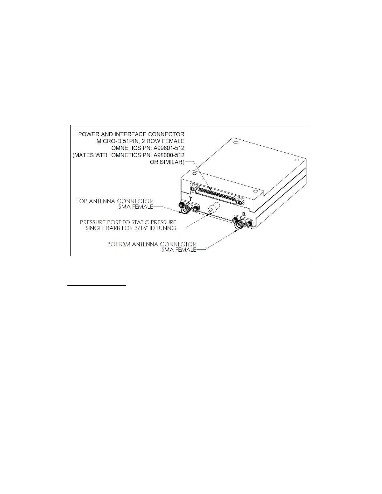
Figure 4-1 shows a labeled diagram of MXS’s connectors and mounting holes, which should be used as a
reference during the installation process.
Note: The Main Connector and its connection to the MXS are described in Section 5.2 Mechanical
Connection and Section 6.0 Electrical Characteristics.
Figure 4-1 Diagram and Identification of MXS Connectors and Mounting Holes Mounting the MXS
4.1 Mounting the MXS
• The MXS needs to be mounted in a location protected from weather.
• MXS should be mounted away from sources of excess heat to better guarantee an operating
environment within its designed temperature range. Mount on a heat sink, if necessary, to
maintain device junction temperature below 85°C. With adequate airflow and lower ambient
operating temperatures, the MXS can be mounted directly to the airframe.
• Refer to Section 5.1 Dimension, Weight & Material for mounting dimensions.
• Sagetech recommends applying Loctite 242 Thread locker to the machine screw threads or using
locking washers or locking nuts.
• The hardware listed in Table 4-2 are potential candidates for use in custom installation.