MXS System Description and Installation Manual UM06945
© Sagetech Avionics 2022 Proprietary Confidential Page 28 of 56
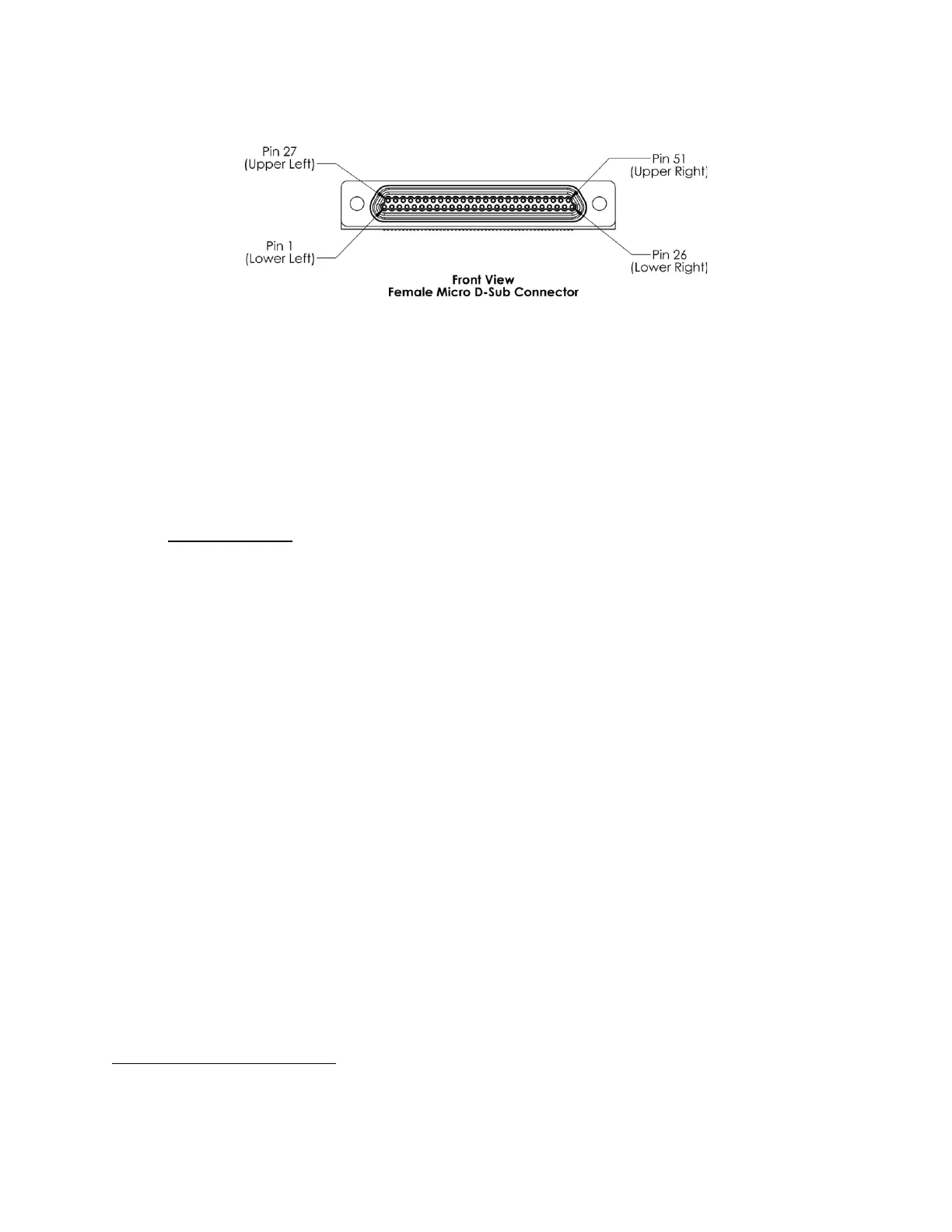
Figure 5-4 Transponder Main Connector - Front View
Connecting the MXS Main Connector to the host requires that a shielded cable be constructed, an example
of which is shown in Appendix A –Shielded Cable Assembly Construction. Refer to AC 43.13-1B Chapter
11 for guidance if new power wiring is required.
6.0 Electrical Characteristics
6.1 Main Connector
Table 6-1 lists the pin assignments for the Main Connector. See Figure 5-4 for pin number orientation.
By design, all signals on the Main Connector are protected from damage caused by Indirect Effects of
Lightning (DO-160G category K3L3
) and Electrostatic Discharge (at 2kV HBM or better) A shielded cable
bundle with similar construction to Appendix A is required. Power specific pins are designed to DO-160G
category B2K1L1.
Additional Main Connector signal information:
• Power signals are the supply voltage and ground returns provided by the aircraft. The DC power
pins of the MXS are protected from overvoltage (up to 50VDC) and reverse polarity conditions.
• The Maintenance Mode signal is a discrete input that allows the flight computer to perform
maintenance functions such as software updates or sending the installation message. To enable
Maintenance Mode, connect the Maintenance Mode pin to ground. To disable Maintenance
Mode, leave the Maintenance Mode pin unconnected, i.e., floating. During normal operation
Maintenance Mode should be disabled.
• MXS Power Control signal is used to power down the transponder (near zero power
consumption). If the Power Control line is left open, the Transponder is powered. The
Transponder will power down when the Power Control line is connected to ground.
• Weight-on-Wheels (WOW) signal is an input that indicates whether the aircraft is on the ground
or in the air. Grounding the pin indicates that the aircraft is on the ground. Removing the ground
indicates the aircraft is in the air. If the WOW signal is not used, the pin may be left unconnected.