MXS System Description and Installation Manual UM06945
© Sagetech Avionics 2022 Proprietary Confidential Page 8 of 56
2.0 System Information
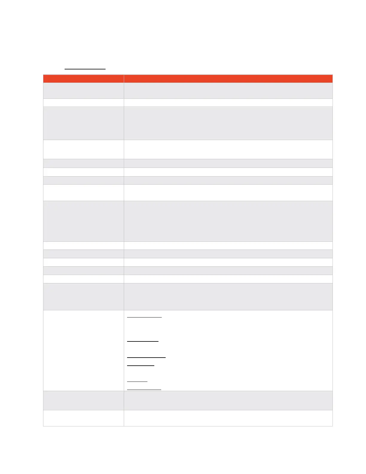
2.1 Specifications
USA (FAA): TSO-C112e, TSO-C166b, TSO-C88b
*See Section 2.2 for specific TSO information
AC20-165B, AC43-6D, AC20-172B, AC20-115C, AC20-152
Environmental: DO-160G (see Environmental Specifications, section 2.9)
Software Category: DO-178C Design Assurance Level C
Hardware Category: DO-254, Design Assurance Level C
Other: DO-181E, DO-260B, AS8003, ARINC 718
ATC Transponder Functionality: 14 CFR 91.215, 91.217, 91.413
ADS-B out functionality: 14 CFR 91.225, 91.227
Width: 2.52in [64.0mm], Height: 1.00in [25.4mm], Depth: 3.50in [89.0mm]
The unit is not required to have a chassis ground. The external chassis is non-
conductive
28VDC 7.5 Watts nominal (20W maximum)
14VDC 7.5 Watts nominal (20W maximum)
Inrush Current <6A
Normal Operation range: 14-28VDC
Minimum and Maximum operating range: 10-32VDC
2x Female SMA Connectors, Female 51pin Micro-D Connector
RS-232, RS-422, Ethernet, GND/Open Discrete Inputs, RF Suppression Bus
-40° to +70°C (-40° to +158°F)
-55° to +85°C (-67° to +185°F)
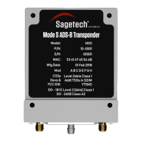
Mode S Transponder
1090ES ADS-B In and Out
Integrated Altitude Encoder tolerance per AS8002
Startup Time: <2 seconds to Transmission,
<20 seconds for BIT to complete and fully functionality
Built in Test: Fault monitoring detailed in SDIM (ICD02373)
ADS-B Receive -79dBm at the antenna, -82dBm at the SMA.
Sensitivity Class A2
Mode S (Class 1 Transponder) 250W - 500W
Transponder Level 2[dels]
The MXS Transponder must be inspected and tested every 24 months
subject to the requirements of FAA documents 14 CFR Part 43 Appendix F.
Repairs performed at the FAA certified Repair Station.