VHF 5000 System Functional unit workshop service
3-25
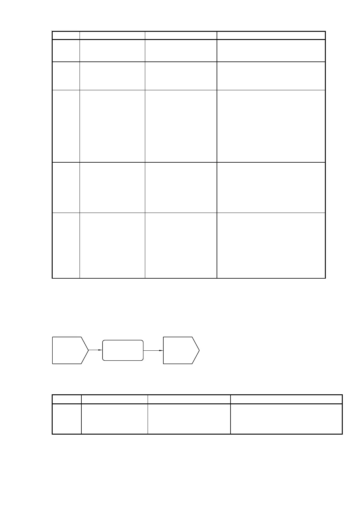
Reference Operation/Test Test Criteria Comments/instructions
RTA-01 Secure antenna connector The antennas must be attached using
original antenna connectors. The connector
is buckled tight onto the antenna bush.
Pass:
None of the listed
messages
Fail:
Otherwise
Pass:
No errors. Though high
temperature protection
messages are allowed.
Error messages should not show while the
unit is used normally
Fail:
Otherwise.
If an RT5020-duplex radio, power cycle
product. Watch for the message (temp too
high…..). In case this message appear, the
product was overheated and automatically
protected by degrading output power.
Pass:
All DSC tests passed. External DSC test
Fail:
External test fails, but
internal test passes
• Do a safety test call to an individual
station or a GMDSS tester.
Internal DSC test
• From the transceiver front select the
internal DSC test command from menu
Pass:
Output power higher
than 25W
Measured with a power meter.
Fail:
See comments on the
right
In case the power is not what was expected
and/or the message “Transmitter output
power not valid” is shown in the display, but
the product seems otherwise functional,
proceed to PA replacement.
During Rx/Tx shifts (PTT) no error messages
with the category: “System malfunction”
must be shown, e.g. Synthesizer lock errors.
RTA-03 Check reports for other
errors in transceiver
display.
RTA-04 Make a DSC test
RTA-05 Check output power
RTA-02 Check reports for severe
RF module errors in
transceiver display.
Tabel 3 (RTA) - Rx/Tx antenna connector tests
(DSCA) - DSC receiver antenna connection
The DSC antenna connection is located on the rear left side of the VHF transceiver (see Section “Interface
connections” in the installation section). If you reach this section of the manual, it is because there are identified
problems receiving DSC calls. Antenna conditions and antenna installations have been checked OK as well.
40427
(RTA-flow)
Proceed from
RTA-02
(DSCA-01)
Secure antenna
connector screw
(Installation)
Aerials and
cable check
OK
40427
(RTA-flow)
Proceed from
RTA-02
(DSCA-01)
Secure antenna
connector screw
(Installation)
Aerials and
cable check
OK
Fig. 8 (DSCA) - DSC antenna connection
Reference Operation/Test Test Criteria Comments/instructions
DSCA-01 Secure antenna
connector
The antennas must be attached using
original antenna connectors. The connector
is buckled tight onto the antenna bush.
Tabel 4 (DSCA) – DSC antenna connector tests.
1007