20
Smarty 2X/3X V
www.salda.lt
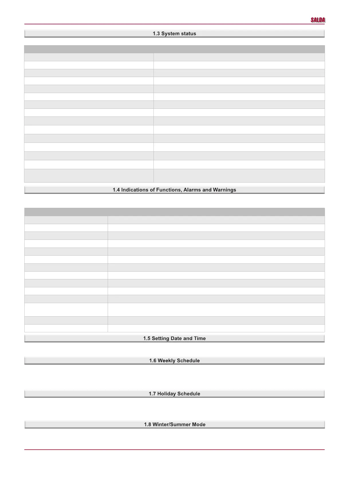
The eld of a system status is designed to notify a user of the existing system status. The table below provides possible system statuses.
System status Description
Stand-by mode System operates in stand-by mode.
Building protection mode System operates in building protection mode.
Economy mode System operates in economy mode.
Comfort mode System operates in comfort mode.
Emergency run System operates in emergency mode. For more information see alarms.
Preparing System is preparing for operation (pre-heating water heaters, etc.).
Opening dampers Dampers are opened.
BOOST function activated “BOOST” function is active.
Cooling heaters Electric heaters are cooled down prior to stopping fans.
Closing dampers Dampers are closed.
Critical alarm Critical failure, system is shut down. For more information see alarms.
Fire alarm Fire protection from an external contactor is activated.
Heat exchanger frost protection activated Heat exchanger frost protection is activated.
Change lters Warning on clogged lters. Pressure relays are activated or lter timer is activated.
Room RH 3 days average is lower than 30%. Limiting 3 speed. Protection against dryness is activated. Room 3-day humidity average is lower than
30%. Air ow is reduced.
Function indications are designed to inform a user on active functions and on the presence of at least one warning or alarm. The table below provides
indications and their descriptions.
Functions indications Description
Working indication output Working indication output is activated
Alarm indication output Failure indication output is activated
System mode switch Mode is activated from an external contactor
Custom fans speed switch Selected fan speed from an external contactor is activated
Winter Active winter mode
Stand-by mode blocking activated Stand-by mode blocking is activated
Slowing down fans Fans are slowed down
Slowing down fans by temperature Fans are slowed down based on supply air temperature
Night cooling function activated Night cooling function is activated
Hydronic pump exercise activated Preventive maintenance of circulation pumps is activated
Service stop function Ventilation logic operation is blocked. Service activities are carried out
Holidays Holiday schedule interval is active. System mode can be changed only upon changing the holiday sched-
ule interval.
Reducing CO
2
level CO
2
reduction function is activated
Full recirculation Full recirculation function is activated
Proper date and time must be set to have proper functioning of schedules, event log and winter/summer function. Fast synchronization with the com-
puter time is possible in user and adjuster environments.
A weekly schedule consists of 10 weekly events. They can be added, deleted, activated and deactivated. One event indicates time, mode and days
of the week.
The system changes modes based on the weekly schedule only when the indicated time comes; therefore a user can always change the existing mode
manually. This schedule noties the user of the upcoming mode change by indicating the time remaining till the next event.
A holiday schedule is used when the unit has to operate in an indicated mode during holidays. The user interface shows when the schedule period is
active as the mode activated by this function (except for protections) can be changed by no-one. In order to control the system in a normal manner,
the holiday schedule period must be deactivated, i.e. zero values must be indicated or period dates must be changed. Up to ve holiday periods can
be indicated.
The winter/summer function is used to set upcoming cold periods, because some part of the system need to be protected against cold outdoor air.
During the winter period it is recommended to leave the unit on, therefore it is possible to set that the system switch-o is blocked during the winter
period. Water heaters must be always on during the entire winter period.
 Loading...