51
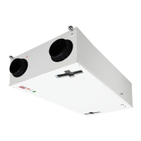
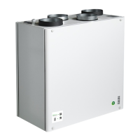
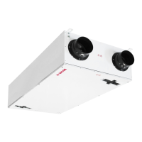
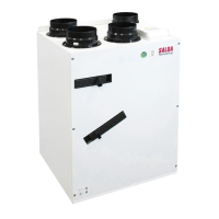
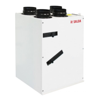
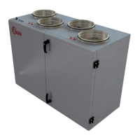
Smarty 2X/3X V
www.salda.lt
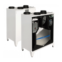
Product Smarty 2XV and Smarty 3XV all versions can be equipped with fresh air damper and extract air drives. They are controlled by 3-point.
Installation diagram.
See “Principle mounting diagram” - 28-30 p.
Wiring diagram.
Automation controller D zone. Upon activation of output X13:3 the dampers shall open, Upon activation of output X13:4 the dampers shall close.
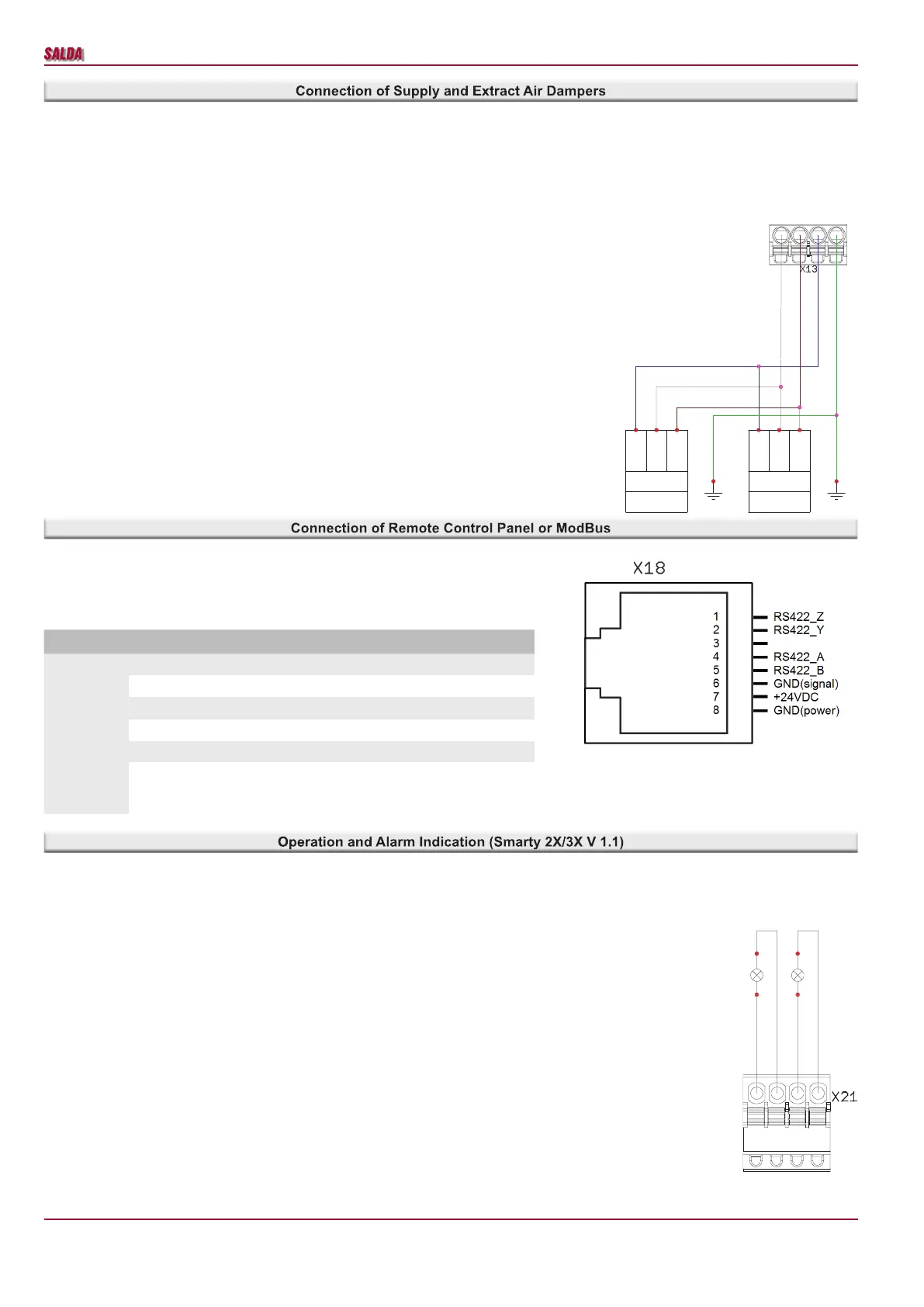
Wiring diagram.
Automation controller F zone, X18 connector.
Switch positions for X18 connector conguration
Switch Position Purpose
S2
1 A+Y (RS422->RS485)
2 B+Z (RS422->RS485)
3 120R line termination resistor
4 1kR line pull-up resistor
5 1kR line pull-down resistor
6
Galvanic isolation disable (turn ON when connecting
Remote Controller - RS_GND will be shorted to GND,
OFF - when connecting to BMS)
Wiring diagram.
Automation controller B zone, X21 connector.
N(L1)
PE
4 3 2 1
230VAC
ON/OFF
N
L1
L1
M3
PE PE
DO4 (L(L2))
DO3 (L(L2))
230VAC
ON/OFF
N
L1
L1
M2
+24VDC
DO1
DO2
+24VDC
1 2 3 4
Alarm
indication
output
(STOP)
Working
indication
output
(START)
H2
H1
 Loading...