44
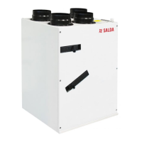
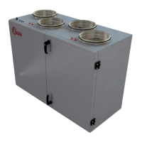
Smarty 2X/3X V
www.salda.lt
C
Connector Contactor No. Contactor name Functional block name
miniEX1
X23
1 DI1
Electric heater manual protection (NC)
2 12VDC
3 DI2
Electric heater automatic protection (NC)
4 12VDC
5 DI3
Filter relay/Fire place I, DI (NC)
6 12VDC
7 DI4
Filter relay/Fire place II, DI (NC)
8 12VDC
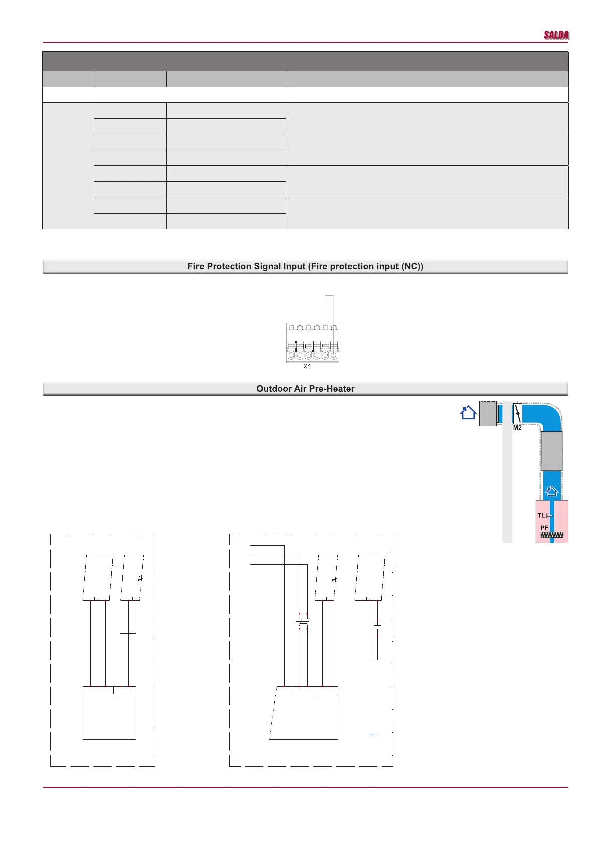
Fire protection signal input must be normally closed, until the re protection system is not connected a jumper is installed in the factory.
Automation controller A zone X4.
In product versions 1.1 pre-heater is integrated inside the product. In product versions 1.2 and 1.3 pre-heater is
integrated on the outdoor air channel. Pre-heater is controlled by 0-10V signal.
Installation diagram.
Installation based on air direction Air Damper M2 -> Pre-Heater PE -> Recuperator.
Wiring diagram.
Automation controller A (X2) and D (X12) zones
1 2 3 4 5 6
DRAWN BY
CHECKED BY
SIGNATUREDUTIES / NAME DATE
UAB"SALDA"
Drawing #
Book #
APPROVED BY
1 2 3 4 5 6 7 8 9 10
External preheater
SP36
1
01
2015-11-27
2015-11-27
X2:5 - GND
X2:6 - AO3(0-10V)
-N1
miniMCB V0.3
X12:1 - PE
X12:2 - N(L1)
X12:3 - DO2(L(L2))
-N1
miniMCB V0.3
External preheater.
Control 0-10V
Power up to 2kW, 1f/230V
PE
N
L1
0-10V
GND
PE1
EKA NIS ... -1F
Max. 2kW/230V
X12:1 - PE
X12:2 - N(L1)
X12:3 - DO2(L(L2))
-N2
miniMCB V0.3
X2:5 - GND
X2:6 - AO3(0-10V)
-N2
miniMCB V0.3
External preheater.
Control 0-10V
Power over 2kW, 2f/400V
-K1
A1
A2
230VAC
1114
-K1
PE
L1
L2
11-GND
12-0-10V
-PE1
EKS NIS ... -2f
-K1
1
2
3
4
PE
L1
L2
KE
(EKA)
+
TA
PE
Ptouch
Stouch
*
TE**
T
inklas
KE*
(EKA)
TA
*
TE**
PE*
(EKA
NIS/
EKA)
KE*
(EKA)
TA
*
TE**
PE*
(EKA
NIS/
EKA)
AKS***
AKS***
AKS***
AKS***
AKS***
AKS***
*
*
*
MB-
Gateway
Ptouch
Stouch
T
inklas
MB-
Gateway
Ptouch
Stouch
T
inklas
MB-
Gateway
 Loading...