21
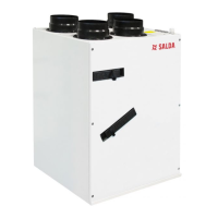
Smarty 2X/3X V
www.salda.lt
Boost ventilation function is used for fast ventilation of the rooms. This function activates the maximum air ow (speed 4). Boost ventilation must be
temporary, i.e. it must be a nal condition (e.g. CO
2
limit, time). The reason for this limitation is protection against dryness. The function is activated
manually and from the external system contactor.
The function is inactive in stand-by mode. Time limit shall be set to this function. Once the function is activated, the indicated time is set for the function
timer and time is counted till the function deactivation. This time may be adjusted in real-time, i.e. when the function is on.
The winter mode may be indicated:
• Manually
• By date
• Based on 3-day mean outdoor air temperature. The mean is calculated only when the fresh air (outdoor) pre-heater is o.
This function is designed to protected premises against dryness. If the function is active, it calculates the 3-day mean humidity of extract air from the
premises. If the mean drops below 30%, fans start operating at speed 2 in comfort mode. A user is notied of the activated protection and limited air
ow.
If the humidity mean exceeds 30% or the function is switched o manually, fans start operating at speed 3 in comfort mode.
This function is designed to save energy which is used to cool a building in the morning by cool night air.
If the function is on but not active, activation conditions are checked:
1 - System time is between function start and function end (hours/minutes).
2 - Time is every hour since the start.
3 - If “Stand-by” mode is set, the unit operates in “Building protection” for 5 minutes so that the actual temperature data is available. Temperatures
are checked after purging. If wrong temperatures are received the unit returns to “Stand-by” mode.
4 - Outdoor temperature is higher than the set outdoor temperature.
5 - Extract air temperature is higher than the set temperature.
6 - Extract air temperature is higher than the outdoor temperature by at least 2 °C.
7 - Summer time.
If all conditions are fullled the unit starts operating in “Comfort” mode (without temperature maintenance). The main window shows that the night
cooling function is active.
Where the function is active, the deactivation conditions are regularly checked:
1 - Time does not correspond to the start/end interval.
2 - Extract air temperature drops below the set point.
3 - Outdoor air temperature drops below the set point.
4 - Mode other than “Comfort” was switched or the unit has been shut down
If at least one condition is correct, the unit switches o the night cooling function and it switches to the mode that was on prior to activating the function.
The air lter timer is designed to inform the user on lter replacement. After lters have been replaced, the timer must be reset. The user can always
see how many days remain till the lter replacement. When the time expires, the warning on lter replacement is displayed. The lter timer limit can
be set in the service environment. Maximum permissible time – 1 year. Time is calculated only when fans are rotating.
This timer also shall be automatically reset to cancel lter clogging warning.
The system noties the user of system failures by alarms and warnings. Warnings are cancelled automatically, whereas alarms must be cancelled
manually. It is recommended that alarms are cancelled by a specialist prior to nding out the causes of the alarm. If at least one alarm is active, the
system is shut down and external failure indication is activated. All possible alarms and warnings are provided in the table below.
ALARMS
NO REGISTER NAME
A1 #D2 FIREPLACE PROTECTION ACTIVATED
A2 #D5 PLATE HEAT EXCHANGER FROST PROTECTION. SYSTEM STOPPED.
A3 #D6 PLATE HEAT EXCHANGER FROST PROTECTION (PRESSURE RELAY). SYSTEM STOPPED.
A4 #D7 HYDRAULIC HEATER FROST PROTECTION. SYSTEM STOPPED.
A5 #D10 TOO LOW SUPPLY TEMPERATURE. SYSTEM STOPPED.
A6 #D11 TOO HIGH SUPPLY TEMPERATURE. SYSTEM STOPPED.
A7 #D12 CHANGE SUPPLY FILTER (PRESSURE RELAY). SYSTEM STOPPED.
A8 #D13 CHANGE EXTRACT FILTER (PRESSURE RELAY). SYSTEM STOPPED.
A9 #D15 CHANGE SUPPLY AND EXTRACT FILTERS. SYSTEM STOPPED.
A10 #D24 SUPPLY AIR TEMPERATURE SENSOR FAILURE. SYSTEM STOPPED.
A11 #D25 EXTRACT AIR TEMPERATURE SENSOR FAILURE. SYSTEM STOPPED.
 Loading...

