49
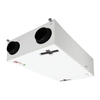
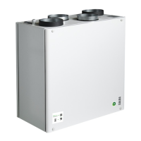
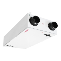
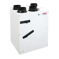
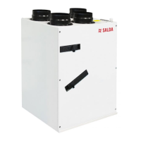
Smarty 2X/3X V
www.salda.lt
Smarty 2X/3X V 1.2 and 1.3 versions of the product can be connected which an electrical heater, which can be controlled by
- On/O signal EKA;
- 0-10V signal EKA NIS.
Installation diagram
The electrical heater shall be installed in the air duct. The arrangement procedure in the direction of air: electrical heater -> TJ supply air sensor.
KE
Mini MCB
TJ
Connection diagrams SP55 and SP56:
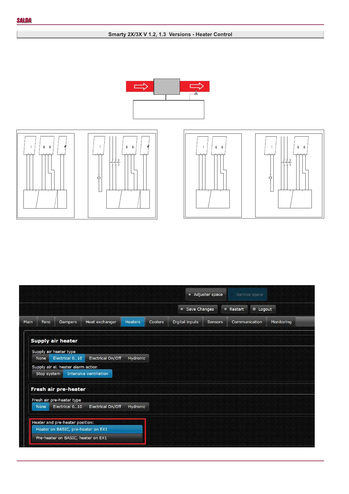
Since a pre-heater is to be connected according to the factory settings, settings should be changed in the environment of the MB-Gateway WEB ap-
plication service or on the Ptouch control panel
1
.
Settings in the environment of the MB-Gateway WEB application service
Change the settings as follows:
• Service password 4444;
• Service -> Heaters -> Heater and pre-heater position;
• Select either the heater or pre-heater to be switched on MiniMCB basic.
1
With the Stouch control panel, it is impossible to change the settings
DRAWN BY
CHECKED BY
SIGNATUREDUTIES / NAME DATE
UAB"SALDA"
Drawing #
Book #
CHECKED BY
1 1 2 3 4 4 5 6 7 7
External heater
SP55
Principle connection scheme
12
02
2016-06-16
2016-06-16
2016-06-16
PE
L
N
KE1
X10:1 - PE
X10:2 - DO1(L(L2))
X10:3 - N(L1)
miniMCB V0.2
X10:1 - PE
X10:2 - DO1(L(L2))
X10:3 - N(L1)
miniMCB V0.2
-K1
1
2
3
4
5
6
-K1
A1
A2
X5:1 - DI5
X5:2 - +12VDC
X5:3 - DI6
X5:4 - +12VDC
miniMCB V0.2
AT1
AT1
RT1
RT1
X5:1 - DI5
X5:2 - +12VDC
X5:3 - DI6
X5:4 - +12VDC
miniMCB V0.2
X2:5 - GND
X2:6 - AO3(0-10V)
miniMCB V0.2
0-10V
GND
0-10V
GND
PE
L
N
KE1
AT1
AT1
RT1
RT1
X2:5 - GND
X2:6 - AO3(0-10V)
miniMCB V0.2
=miniMCB1 =miniMCB1
External heater
Control 0-10V
Power up to 0,6 kW - 1f
External heater
Control 0-10V
Power over 0,6 kW - 1f
DRAWN BY
CHECKED BY
SIGNATUREDUTIES / NAME DATE
UAB"SALDA"
Drawing #
Book #
CHECKED BY
1 1 2 3 4 4 5 6 7 7
External heater
SP56
Principle connection scheme
12
03
2016-06-16
2016-06-16
2016-06-16
PE
L
N
KE1
X10:1 - PE
X10:2 - DO1(L(L2))
X10:3 - N(L1)
miniMCB V0.2
X10:1 - PE
X10:2 - DO1(L(L2))
X10:3 - N(L1)
miniMCB V0.2
-K1
1
2
3
4
5
6
-K1
A1
A2
X5:1 - DI5
X5:2 - +12VDC
X5:3 - DI6
X5:4 - +12VDC
miniMCB V0.2
AT1
AT1
RT1
RT1
X5:1 - DI5
X5:2 - +12VDC
X5:3 - DI6
X5:4 - +12VDC
miniMCB V0.2
PE
L
N
KE1
AT1
AT1
RT1
RT1
External heater
Control on/off
Power up to 0,6 kW - 1f
External heater
Control on/off
Power over 0,6 kW - 1f
=miniMCB1 =miniMCB1
 Loading...