48
Smarty 2X/3X V
www.salda.lt
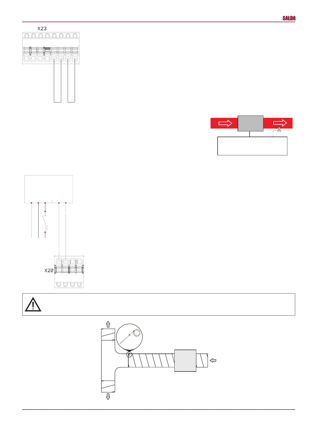
• Automatic and manual protection shall be connected to EX1 controller X23 connector if the electric heater is
equipped with these connection terminals.
• Otherwise jumpers are installed on X23 connector protection inputs.
- Electric heater control 0-10V.
Installation diagram.
Electric heater shall be installed inside air duct. Arrangement based on air
direction Electric Heater -> Supply Air Sensor (TJ).
Wiring diagram.
0-10V heater connection. Automation controller B zone, X20 connector.
+12VDC
DI2
DI1
+12VDC
DI4
DI3
1 2 3 4 5 6 7 8
+12VDC
+12VDC
KE
Mini MCB
TJ
0-10V
AO1 (0-10V)
1 2 3 4
GND
PE
N
L1
GND
0-10V
EKA NIS ... -1F
-Q1
PE N L1
1f, 230VAC
EKA
TJ
When using the supply air heater, the supply air sensor
(SS) shall be installed downstream the heater (or cool-
er) as the sensor cable allows or until the rst branch-
ing, bend of the air transportation system.
 Loading...