INSTALLATION
Please read the important safety information at the start
of this manual before you begin to install the device.
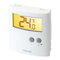
The ideal position to locate the ERT50 230v digital room
thermostat is about 1.5m above floor level. It should be
mounted in a location where the thermostat is easily
accessible, reasonably lit and free from extremes of
temperature. The electrical connections to the ERT50
230v are made to the internal terminal strip. Connection
details are shown below - no Earth connection is required
for the correct and safe operation of the thermostat as the
device is double insulated.
After installing the ERT50 230v in a suitable location, wiring
connections can be made as shown above. The following
criteria apply to the installation:
• The incoming AC mains supply should be 230v AC
and fused at 2 amps.
• Optimum cable size for installation is 1.5 mm
2
; wiring
colours should be in accordance with the current
requirements of the IEE Wiring Regulations.
• All wiring connections should be securely made, and be
firmly terminated within each of the terminal screw clamps.
Do not restore the mains supply to the system until all
associated items are fully installed.
ERT50 230v INSTRUCTION MANUAL
4
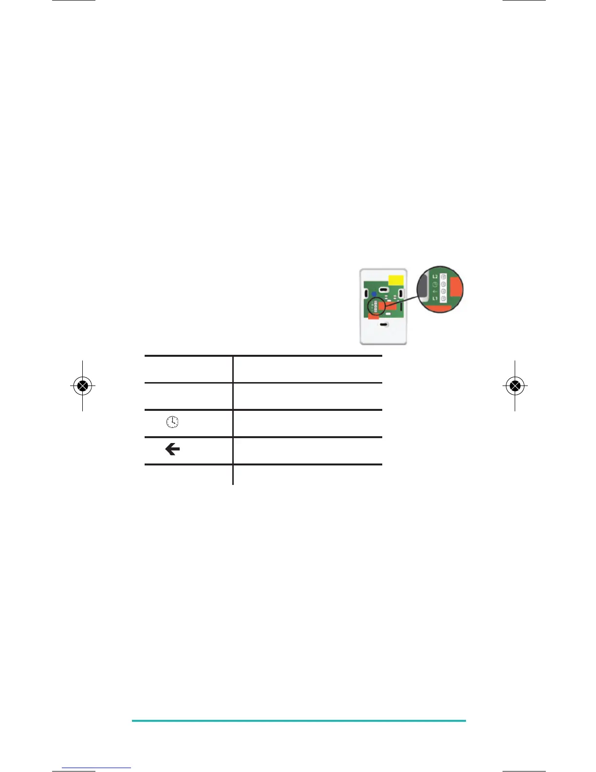
TERMINAL CONNECTIONS
Take the wiring only in accordance
with the wiring diagram below:
230v Version
Connection
L2 Line 2
Supply reduction
Switching output
L1 Line 1