AIS 3410, Electronics Unit
ED3047G842 / 01 (2009-08)
Technical Manual
4 Functional Description
4.3 Description of the Components
t_ue_e04.fm / 27.08.09
33
4.3 Description of the Components
4.3.1 AIS 3410 Electronics Unit
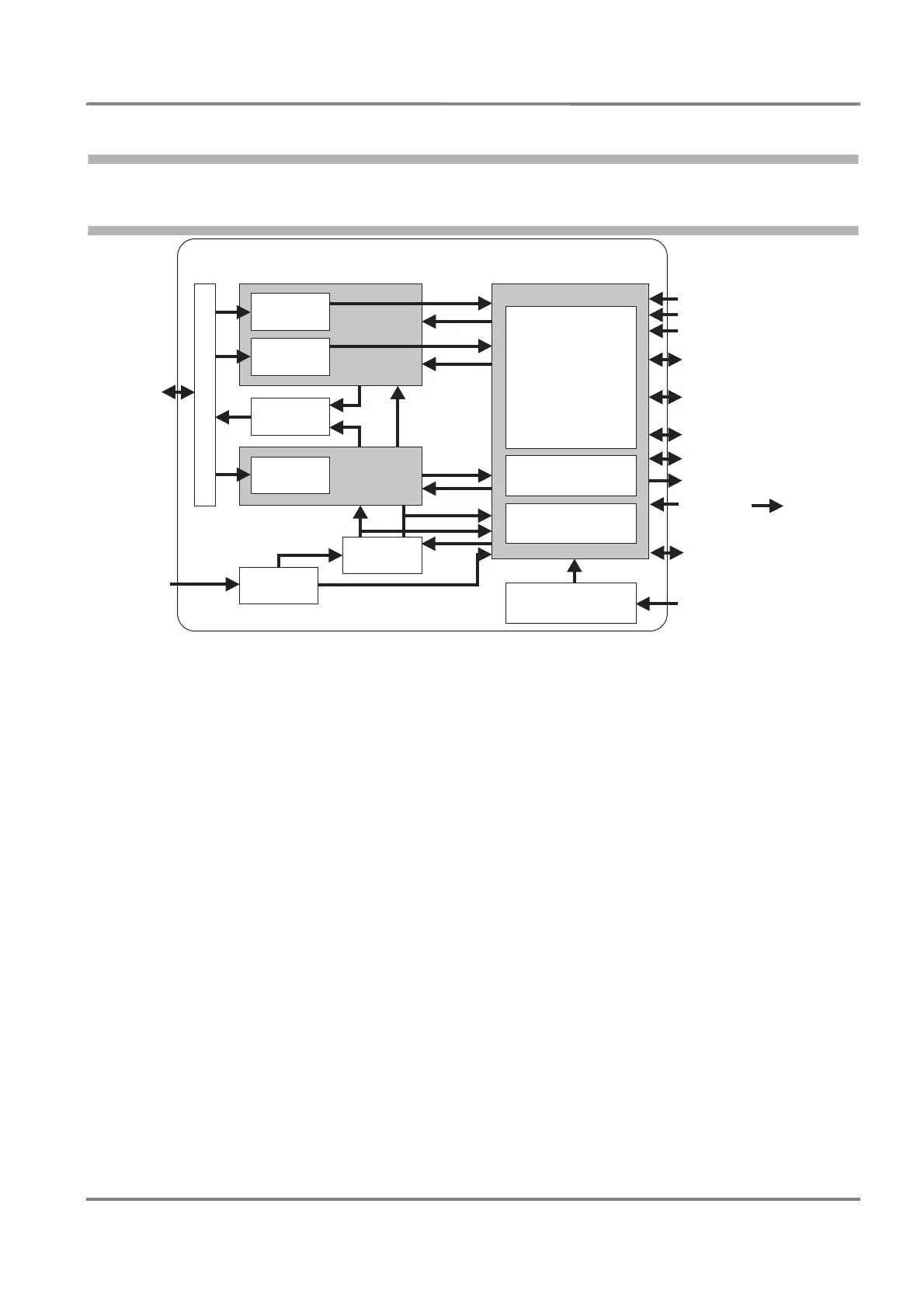
Fig. 4-3 Block diagram of the Electronics Unit
The diagram Figure 4-3 shows the internal structure of the AIS Electronics Unit with the following parts:
VHF Radio
• VHF Receiver:
• AIS Channel A
• AIS Channel B
• DSC Channel 70
• VHF Transmitter:
• AIS Channel A
• AIS Channel B
• DSC Channel 70
GPS
• 16-channel GPS chip
Motherboard and Peripheral Components
• Motherboard pcb
• Processors for the digital signal processing
• 3 interfaces IEC 61162-1/2 for ship’s sensor data input
• Long range port IEC 61162-2
• Primary display port IEC 61162-2 and pilot port IEC 61162-2
• Ethernet interface
• Built-in Integrity Test (BIIT)
• Power supply (input 24 VDC -20%, +20%)
Electronics Unit Interfaces
and Displays
Antennas
Mainboard
AIS
DSC
BIIT
Power
Supply
AIS - A
Receiver
AIS - B
Receiver
VHF antenna
Sensor Input Channels
RS422, IEC 61162 -1/2
(4800/38400 Baud)
Long Range Port, RS422
IEC 61162 -2 (38400 Baud)
Primary Display Port, RS422
IEC 61162 -2 (38400 Baud)
Pilot Port, RS422
IEC 61162 -2 (38400 Baud)
Ethernet Module
24 VDC
Internal Position Sensor
GPS antenna
Transmitter
VHF Antenna Module
DSC
Clock
GPS
Service Port, RS232
RTCM Data
RS422,
IEC 61162 -1
(4800 Baud)