AIS 3410, Electronics Unit
ED3047G842 / 01 (2009-08)
Technical Manual
6 Repair/Maintenance
6.1 Trouble Shooting
t_ue_e07.fm / 27.08.09
50
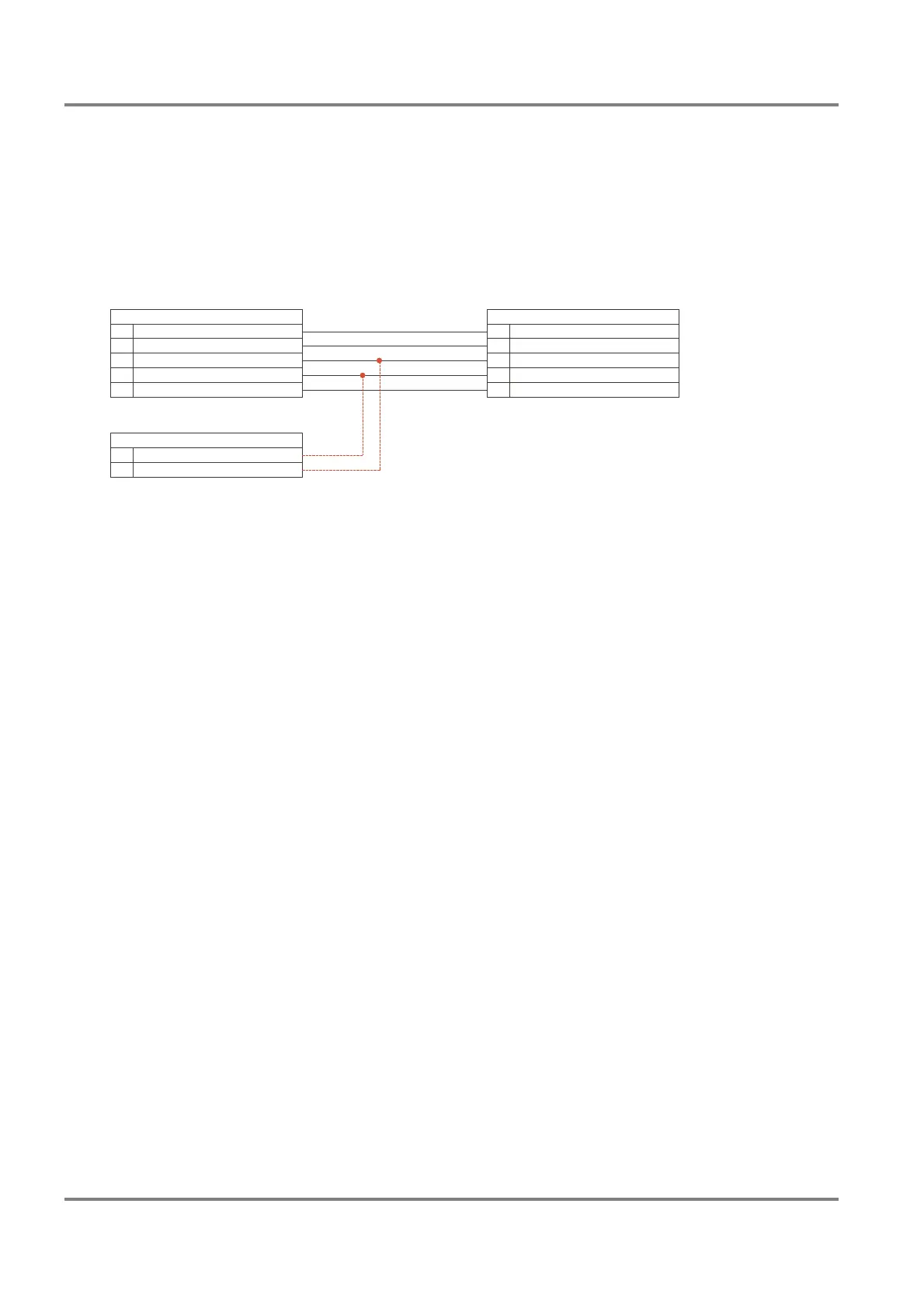
2. Connect the AIS output TB14 and TB15 of the Analog Interface additionally to an indicator serial
interface (TB1) of the radar. If there is a free input, this one should be used. If all inputs are used,
one of them must be disconnected.
Figure 6-1 shows the connection to the serial interface No. 4 as
an example.
Fig. 6-1 Cable connection for the interface monitoring Radar > AIS
3. Power on the radar. Configure the concerned indicator serial interface by means of the System Main-
tenance Manager as follows
Path:
Configure > Radar > Indicator > Indicator x > Serial Interfaces > Serial I/O x
Parameters:
- Driver, set to NMEA183 (IEC 61162-1/2)
- Baud Rate, set to 38400
- Wind, set to Connected (if the interface has been used for a ship’s sensor with NMEA183
(IEC 61162-1/2) protocol beforehand, it is not necessary to modify this parameter.)
4. The Serial I/O Monitor must be started.
Path:
Service > Indicator > Serial I/O Monitor
Select the used interface from the drop down list and mark the check box Rx. Start the monitoring
by clicking on Run. The protocol can be saved on a diskette.
Analog Interface
Interconnection Board
RADARPILOT/CHARTRADAR
MULTIPILOT 1000/1100
AIS Electronics Unit
Primary Display Port
810
16
Output -AIS RxD, Input -
RxD4, Input +
Output +AIS RxD, Input +
RxD4, Input -
Input -AIS TxD, Output -
Input +
GND
AIS TxD, Output +
GND
Connector 2TB
TB1 Indicator Serial Interface 4
614
5
1
15
16
711
17