Do you have a question about the Sam4s ER-420 and is the answer not in the manual?
| Type | Electronic Cash Register |
|---|---|
| Display | Operator: 192 x 64 Graphic LCD with Backlight Customer: 1-Line Alphanumeric |
| Connectivity | RS-232C |
| Printer | Thermal |
| Receipt Printer | Thermal |
Essential safety guidelines to prevent damage and protect against hazards.
Precautions for servicing to avoid hazards and ensure correct reinstallation.
Techniques to prevent damage to ESD components during handling and soldering.
Detailed specifications for the SAM4S ER-420 series electronic cash register.
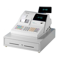
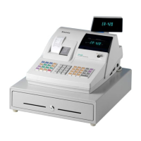
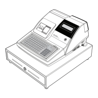
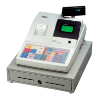
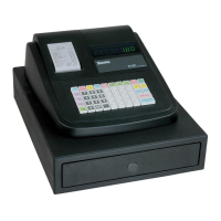
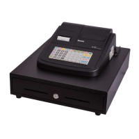
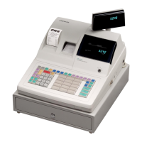
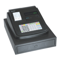
Visual details and dimensions of the electronic cash register's physical layout.
Technical details and parameters for the thermal printer module.
Electrical requirements, consumption, and output voltages for the device.
Technical specifications for various interfaces like RS-232C and EKLZ.
Overview of how the ECR connects and interacts with peripheral devices.
Step-by-step guide for installing paper rolls and other components.
Basic operational modes and functions of the electronic cash register.
Procedures for taking apart the upper section of the ECR's case.
Procedures for taking apart the lower section of the ECR's case.
Guide on how to clean the printer head to maintain print quality.
Visual breakdown of the ER-420M model showing all assembled parts.
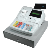
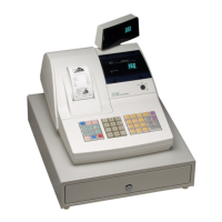
Visual breakdown of the ER-420F model showing all assembled parts.
Detailed parts list and diagram for the printer cover assembly.
Detailed parts list and diagram for the upper case assembly of the ER-420M.
Detailed parts list and diagram for the upper case assembly of the ER-420F.
Detailed parts list and diagram for the STM-320 printer assembly.
Detailed parts list and diagram for the 48-key keyboard assembly.
Detailed parts list and diagram for the lower case assembly.
Detailed parts list and diagrams for the cash drawer assembly.
Layout and component identification for the main printed circuit board.
Layout and component identification for the STM-320 printer PCB.
Layout and component identification for the power switch PCB.
Layout and component identification for front and rear display PCBs.
PCB layout and parts for fiscal boards with different memory sizes.
Layout for the serial interface PCB.
Diagnostic steps for resolving power-related issues in the ECR.
Diagnostic steps for resolving general system malfunctions and failures.
Diagnostic steps for troubleshooting issues with the VFD display.
Diagnostic steps for resolving problems with the thermal printer.
Diagnostic steps for troubleshooting keyboard input and functionality issues.
Diagnostic steps for resolving issues with the drawer or spool motor.
Diagnostic steps for resolving RS-232C communication errors.
High-level block diagram illustrating the ER-420M's internal components and connections.
High-level block diagram illustrating the ER-420F's internal components and connections.
Block diagram detailing the ECR's power supply circuits and voltage outputs.
Detailed pin connection assignments for various ECR interfaces and components.
Detailed schematics for the main printed circuit board components.
Detailed schematics for the power switch PCB.
Detailed schematics for the various display PCBs.
Detailed schematics for the fiscal PCB.
Detailed schematics for the STM-320 printer PCB.
Detailed schematics for the serial interface PCB.