Do you have a question about the Sam4s ER-420F and is the answer not in the manual?
Describes additional information about items within the manual.
Explains symbols used for safety and ESD precautions.
Details safety, servicing, and ESD precautions to prevent damage and hazards.
Provides precautions for safe and effective servicing of the ECR.
Guidelines for handling Electrostatic Sensitive Devices (ESDs) to prevent damage.
Details general technical specifications of the electronic cash register.
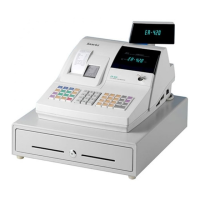
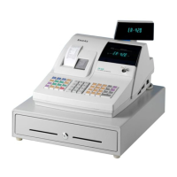
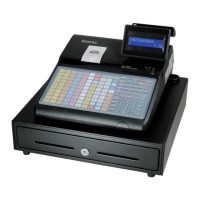
Details appearance dimensions and location features of the ECR.
Details thermal printer specifications, including model, speed, and format.
Specifies character structure, size, pitch, and number of columns for printing.
Details recommended paper type, width, diameter, and thickness for the printer.
Details power consumption, input voltage, and output voltage specifications.
Details RS-232C and EKLZ interface specifications and cable connections.
Illustrates the system configuration with connected peripherals for the ECR.
Provides guidance on installing components and connecting peripherals.
Explains the mode switch functions, keyboard operations, and self-tests.
Step-by-step instructions for disassembling the upper case assembly.
Step-by-step instructions for disassembling the lower case assembly.
Procedure for cleaning the thermal printer head to ensure print quality.
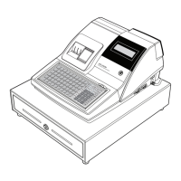
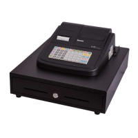
Visual representation of the ECR disassembly for the ER-420M model.
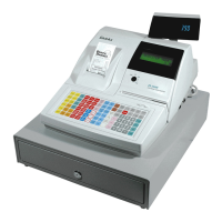
Visual representation of the ECR disassembly for the ER-420F model.
Lists parts for the printer cover assembly.
Lists parts for the ER-420M upper case assembly.
Lists parts for the ER-420F upper case assembly.
Lists parts for the STM-320 printer assembly.
Lists parts for the 48-key raised keyboard assembly.
Lists parts for the case lower assembly.
Lists parts for the drawer assembly.
Lists parts for the housing assembly.
Lists parts for the lock assembly.
Lists parts for the bottom assembly.
Diagram showing the layout of components on the main PCB.
Diagram showing the layout of components on the STM-320 printer PCB.
Diagram showing the layout of components on the power switch PCB.
PCB layouts for front and rear displays (VFD).
Diagram and parts list for the fiscal PCB.
Diagram and parts list for the interface PCB.
Troubleshooting guide for power-related issues in the ECR.
Troubleshooting guide for general system failures and CPU issues.
Troubleshooting guide for issues with the VFD display.
Troubleshooting guide for problems with the thermal printer.
Troubleshooting guide for issues related to the keyboard.
Troubleshooting guide for drawer and spool motor malfunctions.
Troubleshooting guide for RS-232C serial communication errors.
Overall block diagram of the ER-420M electronic cash register.
Overall block diagram of the ER-420F electronic cash register.
Block diagram illustrating the ECR's power supply circuit.
Details pin connections for various connectors on the main PCB.
Detailed schematics for the main PCB, broken down by functional blocks.
Schematic diagram of the power switch PCB and transformer.
Schematics for front and rear VFD display PCBs.
Schematic diagram for the fiscal PCB.
Schematic diagram for the STM-320 printer PCB.
Schematic diagram for the serial interface PCB.
| Type | Electronic Cash Register |
|---|---|
| Paper Width | 58 mm |
| Memory Capacity | 8 MB |
| Cash Drawers | 1 |
| Display | LCD |
| Printer | Thermal printer |
| Cash Drawer | 5 bill, 5 coin |
| Connectivity | USB, RS-232 |
| Power Supply | AC 100-240V, 50/60Hz |