EB 8015 EN 5-5
Installation
− The anti-rotation xture does not get
stuck on the yoke and can move free-
ly in the direction of travel.
14. Extend the actuator stem again and
mount the stem connector clamps.
5.3.1 Mounting the external
anti-rotation xture
Before mounting the actuator, the external
anti-rotation xture must be mounted onto
the plug stem in some cases. The valve must
be closed beforehand.
For SAMSON Type3271 and Type3277
Actuators with Type3273 Hand-operated
Actuator, observe the mounting and operat-
ing instructions of the hand-operated actua-
tor (handwheel) to mount the anti-rotation
xture uEB8312-X.
Standard version for valve sizes DN200/
NPS8 and larger
See Fig.5-1 and Fig.5-2
1. Insert ball bearings (310) into the recess-
es in the bonnet.
2. Place the yoke (3) on the bonnet in such
a way that the ball bearings t into the
recesses of the yoke.
3. Fasten the yoke (3) using the castellated
nut (92).
4. Fasten the hanger (83) and warning la-
bel (255), if applicable, to the yoke us-
ing the screws (82).
5. Position the travel indicator scale (84) on
the hanger (83) with the screws (85) ac-
cording to Table5-3.
6. Use a soft-faced hammer or lever press
to press the slider disks (309) with their
beveled part rst (without using any lu-
bricant) into the recesses of the clamps
(301) as far as they will go. Remove any
excess material.
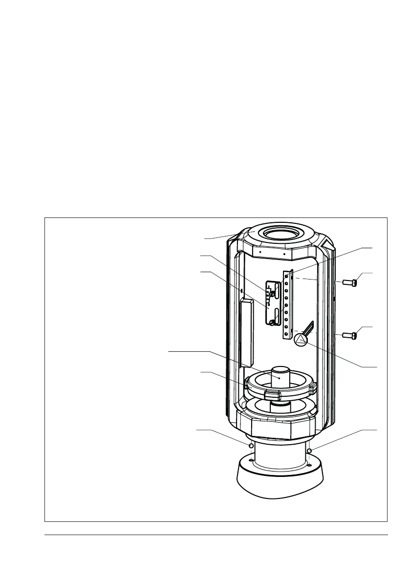
3
83
82
82
310310
92
84
85
255
Legend
3 Yoke
82 Screws
83 Hanger
84 Travel indicator scale
85 Screws
92 Castellated nut
255 Warning label
310 Ball bearing
Plug stem
Fig.5-1: Overview of yoke assembly with travel indicator scale

 Loading...