5-4 EB 8039 EN
Installation
5.3.1 Mounting the actuator
onto the valve
Risk of personal injury due to preloaded
springs.
The valve is tted with an actuator with pre-
loaded springs that are under tension.
Î Before starting any work on the control
valve, relieve the compression from the
preloaded springs. See 'Relieving the
spring compression in the actuator' in the
'Removal' section.
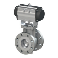
TheType3351ControlValveisdeliveredby
SAMSON with the actuator ready mounted
on the valve.
5.3.2 Installing the valve into
the pipeline
Premature wear and leakage due to insuf-
cient support or suspension.
Î Support or suspend the valve sufciently
at suitable points.
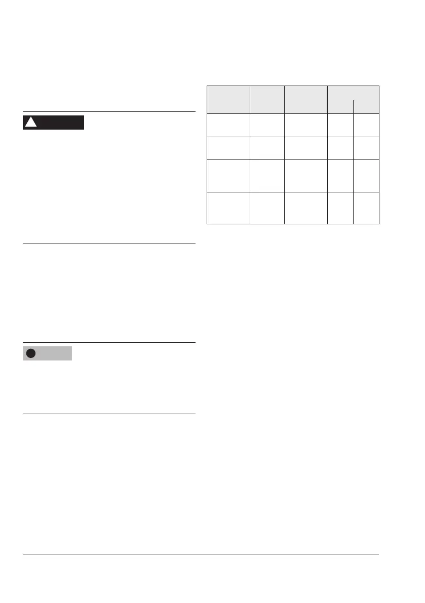
Directionofow
Thedirectionofthemediumowinthevalve
depends on the process medium and the se-
lected fail-safe action:
Table5-2: Direction of ow
Fail-safe
action
Process
medium Valve size
Flow direction
AB BA
Fail-close Vapor/gas
DN15to80
NPS½to3
FTC
1)
–
Fail-close Vapor/gas
DN100
NPS4
– FTO
1)
Fail-close Liquid
DN15to
100
NPS½to4
– FTO
1)
Fail-open
Vapor/
gas/liquid
DN15to
100
NPS½to4
FTO
1)
–
1)
FTO(ow-to-open)
FTC(ow-to-close)
Installing the control valve
1. Closetheshut-offvalvesinthepipeline
at the inlet and outlet of the plant section
while the valve is being installed.
2. Prepare the relevant section of the pipe-
line for installing the valve.
3. Remove the protective caps from the
valve ports before installing the valve.
4. Lift the valve using suitable lifting equip-
ment to the site of installation (see infor-
mation under 'Lifting the valve' in the
'Shipment and on-site transport' section).
Observetheowdirectionthroughthe
valve(seeprecedingparagraph“Direc-
tionofow”).
5. Makesurethatthecorrectangegaskets
are used.
6. Bolt the pipe to the valve free of stress.
7. Attach a support or suspension on the
valve, if necessary.
WARNING
!
NOTICE
!