4 Status and diagnostic alarms
4.1 Standard EXPERT diagnostic
alarms
The standard EXPERT diagnostics provides
information about positioner states such as
operating hours counter, process monitor
-
ing, number of zero calibrations and
initializations, total valve travel, tempera
-
ture, initialization diagnostics, zero/control
loop errors, etc.
In addition, the standard EXPERT diagnostics
generates diagnostic and status alarms
which allow faults to be pinpointed quickly
when a fault occurs.
The diagnostic and status alarms issued by
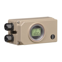
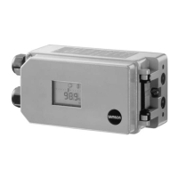
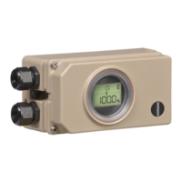
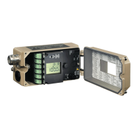
EXPERT appear on the positioner display
and can also be viewed in TROVIS-VIEW
software in the
Diagnosis
folder (>
Status
messages
).
Alarms are classified in the following main
groups:
4
Status
4
Operation
4
Hardware
4
Initialization
4
Data memory
4
Temperature
Further information on the positioner status
(e.g. limit switches, tight-closing function)
and the parameters (e.g. characteristics) are
displayed in the
Positioner
folder).
The following folders contain particularly in
-
formative data for valve diagnostics:
4
Positioner
folder (process data)
Information on the current process vari
-
ables, condensed status, operating
mode, limit switch, temperature.
The Trend Viewer function (activate Trend
Viewer in the
View
menu) allows process
variables to be shown in one or more
graphs.
To proceed, drag and drop the required
process variable into the graph.
4
Positioner
folder (>
Error control
)
Information on total travel with a freely
defined limit
4
Positioner
folder (>
Start-up
>
Initializa-
tion
)
List of initialization errors which can also
be found in the
Diagnosis
folder (>
Sta-
tus messages
).
4.2 Extended EXPERT
+
diagnostic
alarms
Further status alarms are generated from the
extensive information gained in the diagnos
-
tic tests of EXPERT
+
which provide the user
with information covering the whole control
valve (see table below).
These status alarms can be viewed in the
Di
-
agnosis
folder (>
Extended
).
An active diagnostic alarm issued by
EXPERT
+
appears on the positioner display
over Code
79.
28 EB 8388 EN
Status and diagnostic alarms

 Loading...

