EB 8355-1 EN 43
Operation
Adjusting the switching point
Move the valve to the switching point and
adjust the tag by turning the adjustment
screw(53)sothattheswitchingpointis
reached and indicated by the LED on the
switchingamplier.
To guarantee the switching under all ambient
conditions, adjust the switching point ap-
prox.2%beforethemechanicalstop
(OPEN/CLOSED).
After tuning the positioner, make sure that
the vent plug of the housing cover faces
downward when the valve is installed.
NOTICE
!
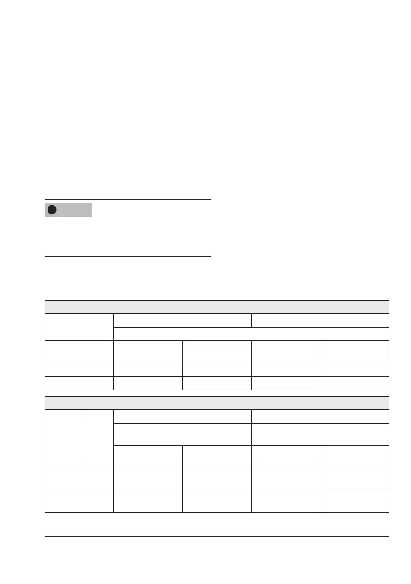
Table8: Direct attachment to Type3277 Actuator (Fig.2)
Left attachment Right attachment
Switch
Valve position Tag outside inductive
eld
Tag inside inductive
eld
Tag outside inductive
eld
Tag inside inductive
eld
Closed B A A B
Open A B B A
Table9: Right or left attachment according to NAMUR (Fig.5) and attachment to rotary actuators (Fig.7)
Direction
of action
Valve
position
Actuator stem extends (FA) Actuator stem retracts (FE)
Switch
Tag
Switch
Tag
Outside inductive
eld
Insideinductiveeld
Outside inductive
eld
Insideinductiveeld
>> Closed
Open
B
A
A
B
A
B
B
A
<> Closed
Open
A
B
B
A
B
A
A
B