42 EB 8355-1 EN
Operation
5.3 Adjusting the limit contacts
The positioner version with inductive limit
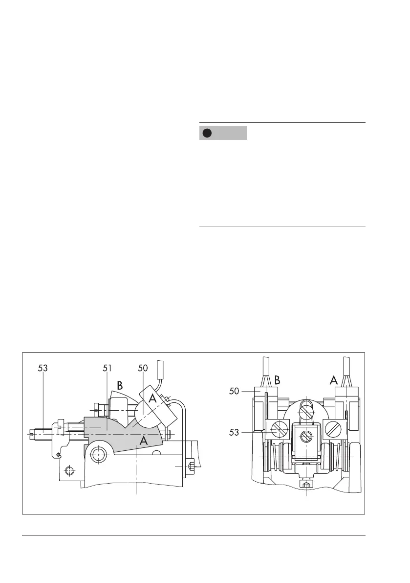
contacts has two adjustable tags mounted on
a rotary shaft which operate the associated
proximityswitches(50).
The operation of the inductive limit contact
requiresswitchingamplierstobeconnected
intheoutputcircuit.Refertosection4.2.1.
Whenthetag(51)islocatedintheinductive
eldoftheswitch,theswitchassumesahigh
resistance.Whenitmovesoutsidetheeld,
the switch assumes a low resistance.
The limit contacts are usually adjusted to is-
sue a signal for both end positions. The
switching points can also be adjusted to in-
dicate intermediate positions.
The switches A and B must be assigned to
the end positions of the control valve (valve
OPEN or CLOSED) depending on the oper-
ating direction and the mounting position ac-
cordingtoTable8andTable9.
Theterminals41/42and51/52canoption-
ally be assigned to the switches A and B by
turning the associated label on the terminal
block(alsoseeFig.11).
The tags of the limit contacts cannot be
turned by 360°. As a result, it is important to
observe the correct assignment of switches A
and B to the valve positions (valve CLOSED
and valve OPEN), especially when the limit
contacts are to be connected in safety cir-
cuits.
The required switching function, i.e. whether
the output relay is to be picked up or re-
leasedwhenthetagenterstheeld,mustbe
determined by jumpers for either load cur-
rent or no-load current at the switching am-
plier.
NOTICE
!
Fig.13: Limit contacts