Connecting the assembly cable
Cable specication
Connecting the cable
Electrical work
(1) For electrical and earth works, comply with the ‘technical standards of electrical installations’ and the the ‘wiring
regulations’ of the Local wiring regulations.
(2) Tightentheterminalblockscrewtounder1.2N•m(12kgf•cm).
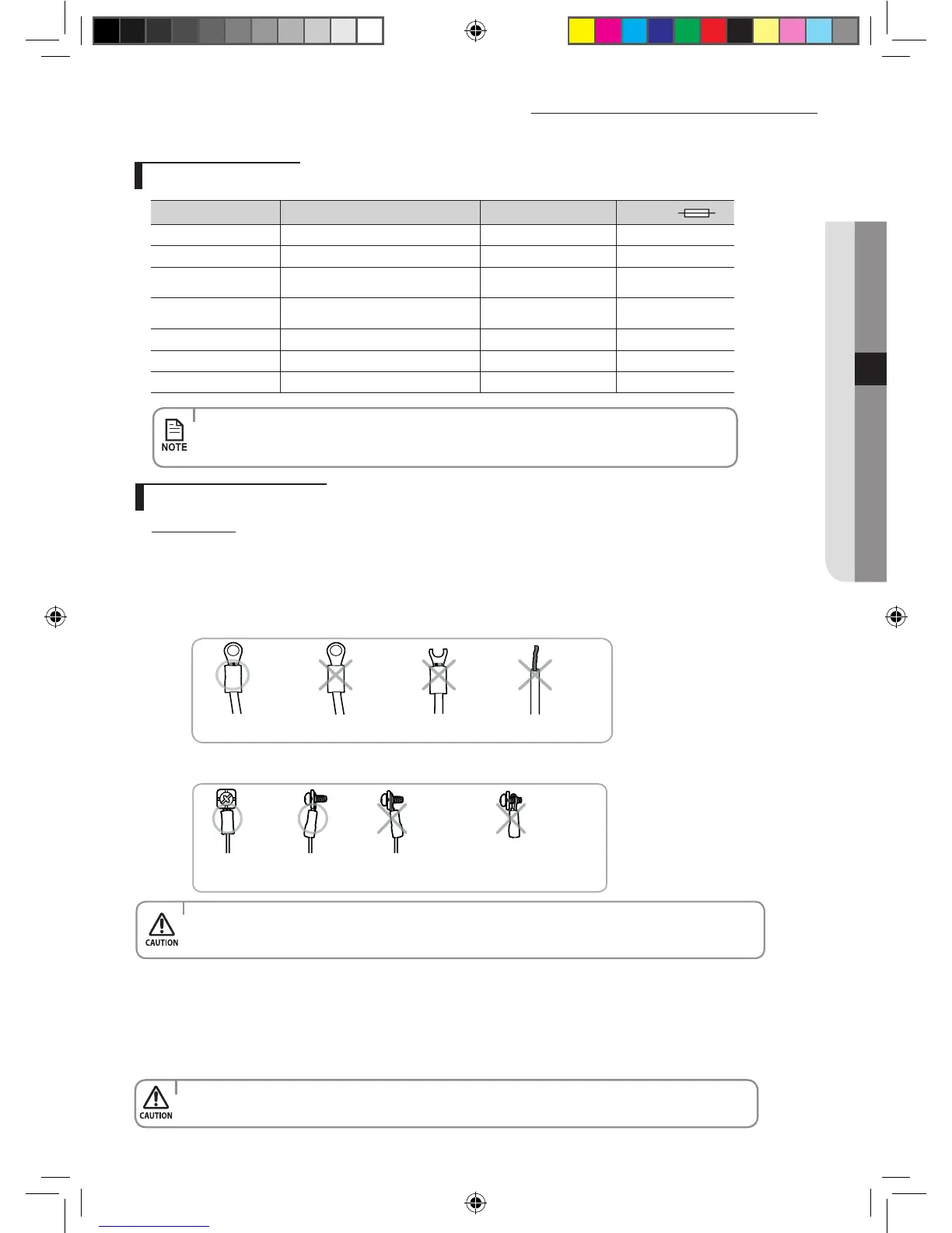
(3) Precautions when connecting terminal blocks of the indoor unit
Before connecting, make sure the connecting part of the terminal socket is facing upwards.
Upside down
The terminal
socketis damaged.
There is no ring
terminalto cover the wire.
There must be no space between the terminal and the screw when connected.
- Any remaining space may become a re hazard due to overheating of the electrical contact.
The terminal socket
is upside down.
Eitherthescrewisnotfitted
properly or there is a space
between the screw and the
ring terminal.
• For the terminal block wiring, use a wire with a ring terminal socket only.
Regular wires without a ring terminal socket may become a re hazard due to overheating of the
electrical contact during a wiring work.
1. Extend the assembly cable if necessary.
• Donotconnecttwoormoredierentcablestoextendthelength.
It may cause re.
When you install the unit, make rst refrigerant connections and then electrical connections.
Connect the air conditioner to grounding system before performing the electrical connection.
If unit is uninstalled, rst disconnect electrical cables, then refrigerant connections.
If the outdoor unit is more than 4 or 5 meters away from the indoor unit, you must extend the cable. The maximum length of
the cable is 15(09/12/18) / 20(24) meters.
Model Power cable Interconnection cable Type GL
AR09/12HCCH
3G1.5mm² H05VV-F 3G1.5mm² H07RN-F 20A
AR18HCCH
3G2.5mm² H05VV-F 3G2.5mm² H07RN-F 25A
AR09/12HPCH
3G1.5mm² H05VV-F
3G1.5mm² H07RN-F
2x0.75mm² H05RN-F
20A
AR18HPCH
3G2.5mm² H05VV-F
3G2.5mm² H07RN-F
2x0.75mm² H05RN-F
25A
AR09/12HCCB/XL
3GxAWG16 SJT (3G1.0mm² H05VV-F) 3G1.0mm² H07RN-F 20A
AR18HCCB/XL
3GxAWG14 SJT (3G1.5mm² H05VV-F) 3G1.5mm² H07RN-F 25A
AR24HCCB/XL
3G2.5mm² H05RN-F 3G2.5mm² H07RN-F 25A
• Connectthepowercabletotheauxiliarycircuitbreaker.Ifeverypolefailstoconnecttothe
power supply, it must be incorporated in a wire with a contact opening of ≥3 mm.
• Useshieldcable(Category5;lessthan50pF/m)fornoisyenvironmentalsite.
English-37
INSTALLATION05
A3050 CB&XL&CH_IB&IM_DB68-04138A_HP&CO_EN.indd 37 2013-12-28 14:43:45