LED R&D Lab(VD)
38
5. Cabinet + Frame Installation
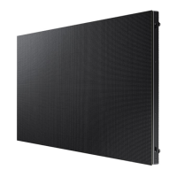
② Draw the cabinet right up against the frames by aligning the cabinet corners with the engravings on the
frames.
※ For the order of installing cabinets, see Fig. 1 on page 18 .
※ Check that the four bolts are all inserted into the frames. (See Fig.1.)
③ Push the top surface of the cabinet corners down so that the cabinet slides down diagonally. (See Fig.2.)
④ From the second row and above, insert the Service Jig between the cabinets and attach
the cabinets. Next, remove the Service Jig and slowly lower the cabinets.
(See Fig.3.)
※ Exercise caution to ensure that the Service Jig does not touch an LED module.
※ Each time a cabinet is installed, check that there is no inter-module gap or pitch interval warning found.
engraved
position
engraved
position
engraved
position
Fig.1
Fig.2
Fig.3
Sliding Screw
◆ Fixing of I/G position

 Loading...


