Installing the Capacitor Control
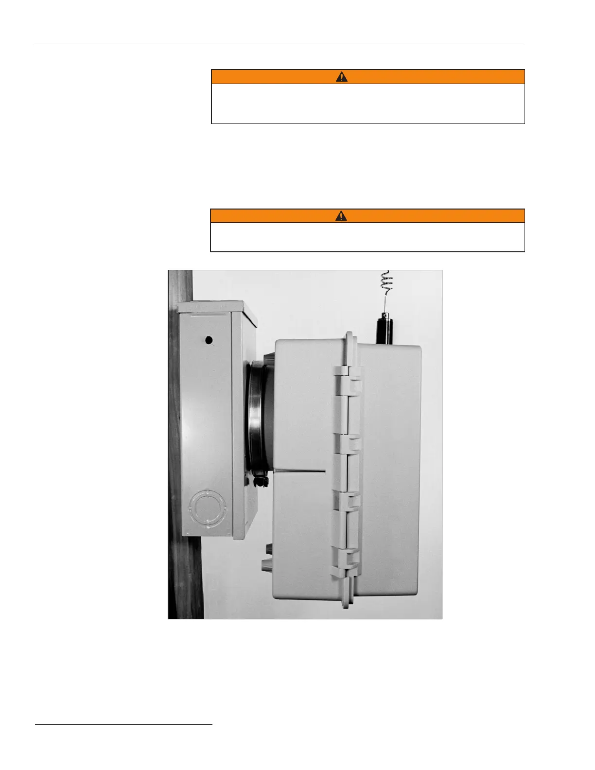
STEP 3. Plug the control into the meter base socket. See Figure 13.
When the control is plugged into an energized meter base, all faceplate
LEDs light momentarily. After a few seconds, the LCD screen will show
**Unit OK**.
Make sure the OPERATION MODE MANUAL and SCADA CONTROL
LOCAL LEDs are lit. If not, press the applicable CHANGE button.
WARNING
The control must be set to Manual and Local mode to avoid unexpected
operation of the capacitor bank during installation or setup operations.
Figure 13. Side view of capacitor control enclosure and meter base, with a snap ring and crimp
lock installed.
STEP 4. Lock the control to meter base.
Use your standard procedure for a locking ring, snap ring, crimp lock, etc.,
and lock the control to the meter base.
STEP 5. Go to the “Harness Wiring” section on page 17.
WARNING
If lightning arresters are installed, their ground path must not go through
the neutral current sensor. Connect them to ground on the earth side of
the sensor.
14 S&C Instruction Sheet 1024-510

 Loading...