Communication Module
STEP 6. Connect the antenna connector to the radio.
STEP 7. Reinstall the radio tray assembly, and replace
and securely tighten the ve ¼–20 bolts. Close
the battery compartment cover, and tighten the
battery compartment cover screw.
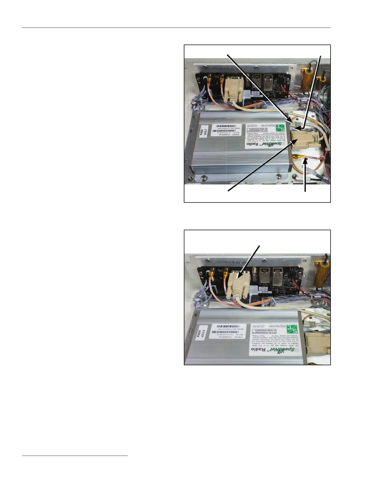
Figure 12. Serial cable connected to the Wi-Fi circuit board.
Serial-to-Wi-Fi connector
Figure 11. Radio installed in the communication module.
Serial-to-Wi-Fi connector
Ethernet connector Power plug
Antenna connector
12 S&C Instruction Sheet 766-520

 Loading...


