s07nmdl1sm-rev0817
sandpi p erpump .com
14 • Model S07 Non-Metallic
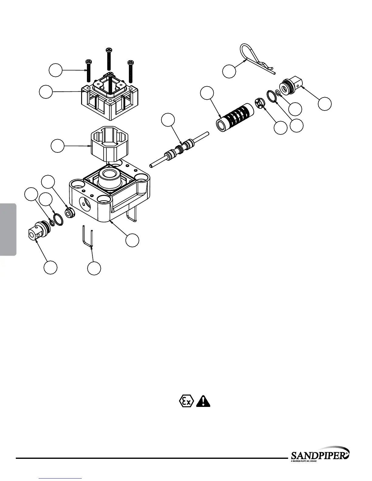
Air Valve with Stroke Indicator Assembly
Note: Stroke Indicator is standard on Spill Containment models
ATEX Compliant
1-E
1-F
1-C
1-D
1-B
1-B
1-A
1-G
1-E
1-F
1-C
1-D
1-J
1-K
1-H
1-I
MAIN AIR VALVE ASSEMBLY PARTS LIST
Item Part Number Description Qty
1 031-167-000 Air Valve Assembly 1
1-A 095-106-559 Body, Air Valve 1
1-B 031-134-000 Sleeve and Spool Set 1
1-C 560-101-360 O-Ring 8
1-D 132.030.552 Bumper 2
1-E 165-123-147 End Cap 2
1-F 560-029-360 O-Ring 2
1-G 675-062-115 End Cap Retainer 2
1-H 210-008-330 Safety Clip 1
1-I 530-031-550 Mufer 1
1-J 165-109-559 Mufer Cap 1
1-K 710-011-115 Self-Tapping Screw 4
For Pumps with Virgin PTFE coated hardware:
1 031-167-002 Air Valve Assembly 1
1-G 675-062-308 End Cap Retainer 2
1-J 710-011-308 Self Tapping Screw 4
(Includes all other items used on 031-166-000 above)
For Pumps with alternate Mesh or Sound Dampening Mufers or Piped
Exhaust:
1 031-169-000 Air Valve Assembly 1
(Includes all items used on 031-167-000 above minus 1-H, 1-I and 1-J)
4: AIR END