s07nmdl1sm-rev0817
sandpi p erpump .com
Model S07 Non-Metallic • 15
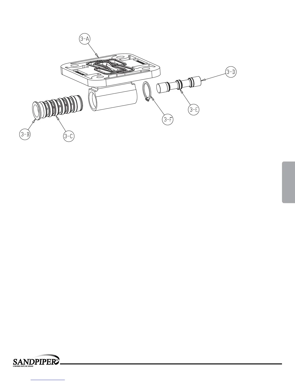
Pilot Valve Assembly
PILOT VALVE ASSEMBLY PARTS LIST
ITEM PART NUMBER DESCRIPTION QTY
3 095-091-000 Pilot Valve Assembly 1
3-A 095-087-551 Valve Body 1
3-B 755-051-000 Sleeve (With O-rings) 1
3-C 560-033-360 O-ring (Sleeve) 6
3-D 775-055-000 Spool (With O-rings) 1
3-E 560-023-360 O-ring (Spool) 3
3-F 675-037-080 Retaining Ring 1
PILOT VALVE SERVICING
To service the pilot valve rst shut off the
compressed air supply, bleed the pressure from
the pump, and disconnect the air supply line
from the pump.
STEP #1: See pump assembly drawing.
Using a 7/16" wrench or socket, remove
the four capscrews (item 12). Remove the air
inlet cap (item 8) and air inlet gasket (item 18).
The pilot valve assembly (item 3) can now be
removed for inspection and service.
STEP #2: Disassembly of the
pilot valve.
Remove the pilot valve spool (item 3-D).
Wipe clean and inspect spool and o-rings for
dirt, cuts or wear. Replace the o-rings and spool
if necessary.
Remove the retaining ring (item 3-F) from
the end of the sleeve (item 3-b) and remove
the sleeve from the valve body (item 3-A). Wipe
clean and inspect sleeve and o-rings for dirt,
cuts or wear. Replace the o-rings and sleeve
if necessary.
STEP #3: Re-assembly of the
pilot valve.
Generously lubricate outside diameter of
the sleeve and o-rings. Then carefully insert
sleeve into valve body. Take CAUTION when
inserting sleeve, not to shear any o-rings.
Install retaining ring to sleeve. Generously
lubricate outside diameter of spool and o-rings.
Then carefully insert spool into sleeve. Take
CAUTION when inserting spool, not to shear
any o-rings. Use BP-LS-EP-2 multipurpose
grease, or equivalent.
STEP #4: Re-install the pilot valve
assembly into the intermediate.
Be careful to align the ends of the pilot
valve stem between the plunger pins when
inserting the pilot valve into the cavity of the
intermediate.
Re-install the gasket, air inlet cap and
capscrews. Connect the air supply to the pump.
The pump is now ready for operation.
4: AIR END