PREPARATION
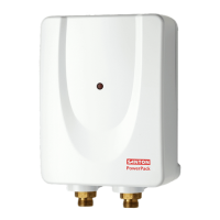
4.1 Remove the xing screw which holds the front cover onto the back plate of the
PowerPack heater. Carefully remove the cover.
4.2 The unit must be mounted on a at surface, which covers the full width and
length of the back plate. It is important that the wall surface is at otherwise
difculty may be encountered when tting the cover.
4.3 DO NOT t the PowerPack to the wall and tile up to the case. It must be tted
on to a nished at and even wall surface. This allows removal for servicing.
CABLE ENTRY
4.4 Cable entry can be from the rear (see Figure 5) or from the bottom.
When opting for bottom entry make cut-out to suit cable before tting back
plate to the wall.
4.5 Fix the PowerPack heater loosely to the wall. The wallplugs provided are
suitable for most brick walls (use a 6.5mm diameter masonry drill), but if your
wall is plasterboard or soft building block, you should use special wallplugs and
an appropriate drill, obtainable from most hardware stores.
PLUMBING
4.6 Decide where to connect to the water mains for your feed to the PowerPack.
Ensure that the pipe you have selected is not a gas pipe or a hot water pipe or
from a cold water storage tank.
4.7 Cut the necessary pipe work to length, assemble and offer up to the installation
before making any soldered joints. Ensure that the pipe is the correct length, as
shortening it can be difcult once joints have been made.
4.8 An isolating stop valve MUST be incorporated to the main water supply to
comply with Water Regulations
4.9 Assemble the installation before making any soldered joints. DO NOT use
jointing compounds on any pipe ttings for the installation.
4.10 Remove the unit before soldering the connections.
4.11 It is essential to ush the pipe in order to clear debris, particles of solder and
swarf.
4.12 Turn the water off after ushing using the isolating stop valve.
4.13 Connect the cold water supply pipe to the inlet of the PowerPack, this is a 1/2”
BSP connection.
4.14 Fit top and bottom screws and secure the back plate to the wall ensuring that it
is level.
4.15 Connect all other components as per Figure 3.
4.16 Turn the isolating stop valve on slowly and check for leaks in all pipe work,
rectify as necessary.
4.17 Turn off the isolating stop valve.
4.18 Place the cover onto the back plate.
4.19 Secure the cover to back plate using screw provided.
4.0 CONNECTING TO SERVICES