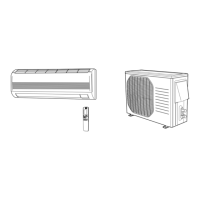
Do you have a question about the Sanyo CH3642 and is the answer not in the manual?
| Type | Split System |
|---|---|
| Power Supply | 220-240V, 50Hz |
| Refrigerant | R410A |
| Operating Temperature (Cooling) | 18°C to 43°C |
| Operating Temperature (Heating) | -5°C to 24°C |
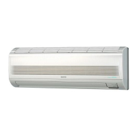
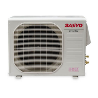
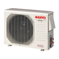
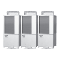
Details general specifications for indoor and outdoor units, including performance and electrical ratings.
Lists specifications for key components like fan motors, coils, and electronic expansion valves.
Provides specifications for auxiliary components such as power transformers, drain pumps, and thermistors.
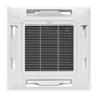
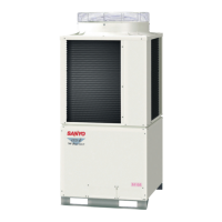
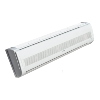
Presents physical dimensions and mounting details for various indoor and outdoor unit types.
Illustrates the refrigerant circuit path for cooling and heating cycles.
Defines the acceptable indoor and outdoor temperature ranges for cooling and heating operation.
Provides detailed cooling capacity data under various temperature and airflow conditions.
Offers comprehensive heating capacity specifications across different operating temperatures.
Includes charts showing operating current and pressure characteristics for various models.
Displays octave band sound pressure levels for different unit types and sound levels.
Explains how to adjust fan speed to improve airflow when external static pressure is high.
Illustrates air throw distances for different indoor unit types under various conditions.
Covers essential guidelines for tubing length and elevation differences between units.
Explains how the unit maintains room temperature by cycling the compressor based on thermostat settings.
Details the function that controls indoor fan speed to prevent cold drafts during heating.
Describes how the indoor fan speed adjusts automatically based on room temperature in AUTO mode.
Explains how the outdoor fan speed is automatically selected based on outdoor temperature.
Outlines the system that prevents the indoor heat exchanger coil from freezing during cooling.
Describes how condensing temperature is managed based on outdoor coil temperature.
Explains the function that prevents the air conditioner from overloading during heating operation.
Details how compressor motor overheating is prevented by controlling discharge gas temperature.
Describes the automatic switching between cooling and heating based on room and set temperatures.
Explains the defrosting system that removes frost from the outdoor coil during heating.
Details the function of the 4-way valve in directing refrigerant flow for cooling and heating modes.
Covers the unit's power failure recovery function, allowing automatic restart after power is restored.
Describes the function and control system of the electronic refrigerant control valve for precise flow adjustment.
Lists temperature ranges for compressor discharge gas during cooling and heating operations.
Explains the circuit that detects compressor current to prevent damage from overcurrent or seizing.
Outlines the control logic for the electronic refrigerant control valve, including fuzzy logic.
Describes the system that protects components from over/under voltage by flashing indicator lamps.
Provides electrical diagrams and schematics for various indoor unit types.
Offers electrical diagrams and schematics for different outdoor unit models.
Guides users through diagnosing and resolving common problems using flow charts and alarm messages.
Details procedures for testing electrical components like fuses, motors, and thermistors for proper function.