Do you have a question about the Sanyo PLC-WM5500 and is the answer not in the manual?
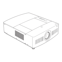
Identifies the product type as a multimedia projector.
Specifies the model number of the projector.
Indicates this is the original version of the service manual.
Lists essential safety measures for servicing the projector.
Highlights safety-critical components and recommends using exact replacements.
Warns about potential hazards like eye damage and electric shock during servicing.
Details physical characteristics like dimensions, weight, and feet adjustment.
Specifies the LCD panel system, resolution, and pixel count.
Lists supported color systems and TV signal formats.
Provides details on projection size, throw distance, lens, and lamp.
Lists available input and output ports and connectors.
Details voltage and power consumption requirements.
Specifies operating and storage temperature ranges.
Lists specifications for the remote control, including dimensions and weight.
Lists accessories provided with the projector, such as manuals and cables.
Describes the fuse type, location, and procedure for replacement.
Explains the function and reset mechanism of the thermal protector.
Details the function of filter cartridge and lamp cover switches.
Lists and explains the function of various LED indicators on the projector.
Describes the function and location of temperature and wind sensors.
Explains protection mechanisms against power failure and fan lock.
Provides step-by-step instructions for replacing the filter cartridge.
Details the procedure to reset the filter and scroll counters via the on-screen menu.
Provides instructions for replacing the projection lamp, including safety precautions.
Explains how to check the total lamp usage time and provides the calculation formula.
Describes procedures for quick access to optical parts for maintenance.
Provides instructions for removing and attaching the projection lens.
Details the procedure for mounting the lens antitheft screw for security.
Covers cleaning optical parts with air spray, disassembly cleaning, and lens/cabinet cleaning.
Explains security functions like Key lock and PIN code lock, and their initial settings.
Provides steps to reset security functions to their initial factory settings.
Presents a flowchart of the basic mechanical disassembly procedures.
Instructions for removing the lamp cover and prism cover.
Steps for removing the cabinet top assembly.
Instructions for removing the fan and main board.
Steps for removing the A/V board assembly.
Instructions for removing shutter, net joint, and sensor C boards.
Steps for removing the lamp assembly, lamp cover, and IC connect board.
Instructions for removing the projection lens.
Steps for removing the optical unit assembly and lens shift assembly.
Instructions for removing the lens shift assembly.
Steps for removing the power box assembly and thermal switch.
Instructions for disassembling the power box and removing the fan.
Steps for removing the control board and associated fans.
Instructions for removing the A/V board assembly.
Steps for removing the duct fan assembly.
Instructions for removing the remaining fans and the speaker.
Instructions for removing the LCD panel/prism assembly.
Explains how to identify the LCD panel type (R or L).
Instructions for removing the polarized glass assemblies.
Steps for removing the PBS and integrator lens assembly.
Instructions for removing the condenser lens assembly.
Steps for removing optical parts within the optical unit.
Instructions for removing the mirror(B) and relay lens(In) assemblies.
Provides a diagram showing the placement of optical parts within the unit.
Details adjustments needed after replacing specific parts.
Explains settings required when replacing the main board, including shipment data and serial number.
Describes how to enter and navigate the service mode menu.
Explains how to temporarily disable the wind sensor function and then re-enable it.
Lists preparatory steps and precautions before performing optical adjustments.
Details how to access and select internal test patterns from the menu.
Instructions for performing optical axis adjustment using test patterns.
Instructions for adjusting the Mirror (B) to eliminate color bands.
Details how to adjust the relay lens (R) to correct color shading.
Instructions for adjusting the condenser lens to remove color shading.
Explains how to adjust contrast using the 'All black' test pattern.
Provides cautions and conditions for adjusting internal circuits.
Details the procedure for adjusting output voltage after replacing the power board.
Explains how to adjust fan voltages using a digital voltmeter.
Describes the process for PC, Component, and Video auto calibration.
Provides manual adjustments if auto calibration fails for PC, Video, or Component inputs.
Steps to adjust common voltage for flicker reduction and color balance.
Explains how to check and set the panel type based on LCD panel installation.
Use of software for obtaining proper gray scale.
Details how to change data values for proper white balance.
Use of software to correct color shading on the screen.
Procedure for calibrating the wind sensor, including important pre-adjustment steps.
Diagrams showing the locations of test points on the Main Board and Power Board.
Table listing initial values for adjustment items and reference data.
Block diagram illustrating the main components and their interconnections.
Guide for diagnosing no power issues based on indicator lights.
Troubleshooting for power supply issues with a detailed circuit diagram.
Troubleshooting steps for fan control issues related to no power.
Troubleshooting guide for lamp control issues causing no power.
Explains the temperature monitoring system and potential causes of overheating.
Troubleshooting steps to diagnose and resolve issues related to no picture output.
Troubleshooting guide for issues where the projector produces no sound.
Troubleshooting steps for issues related to motor control of zoom, focus, shutter, etc.
Explains the bus control system and its components.
Details the LED drive circuits and remote control functions.
Explains how to interpret projector status based on indicator lights.
Table relating indicator light patterns to specific abnormal projector conditions.
Explains the power failure detection system and provides an error information table.
Circuit diagram illustrating the power failure detection system and signal flow.
Diagram showing sensor and detection switch connections and error information.
Explains how to access and reset the projector's error history log.
Procedure for diagnosing power failures using RS-232C communication software.
Details the RS-232C serial port control interface, including communication settings.
Lists serial commands for controlling projector functions.
Explains serial commands for reading projector status and temperature data.
Details the I/O port functions for system control.
Explains the I/O functions for the I/O expander.
Details pin functions for the IIC bus D/A converter related to fan control.
Block diagram for the IC5502 inverter.
Block diagram for the IC001 audio output chip.
Block diagram for the IC5501/IC5521 motor drive.
Block diagram for the IC6502/IC6521 motor drive.
Block diagram for the IC1011 sync separator.
Block diagram for the IC501/IC531/IC561 S&H circuits.
Block diagram for the IC401 digital gamma correction.
Block diagram for the IC601 power factor control.
Block diagram for the IC2201 A/D converter.
Block diagram for the IC7801 DAC.
Block diagram for the IC5541 motor controller.
Block diagram for the IC5001 audio selector.
Block diagram for the PIC18F67 IC.
Block diagram for the IC301 scaler.
Block diagram for the IC2301 keystone correction.
Block diagram for the IC603 power switching.
Block diagram for the IC651 power switching.
Block diagram for the IC4801 I/O expander.
Block diagram for the IC5231/IC5271 3-channel analog switch.
Exploded view of the cabinet top assembly, showing parts and their locations.
Exploded view of the first part of the cabinet bottom assembly.
Exploded view of the second part of the cabinet bottom assembly.
Exploded view of the main, A/V, and Net Joint board assemblies.
Exploded view of the filter box assembly.
Exploded view of the power box assembly.
Exploded view of the projection lens and optical unit.
Exploded view of the LCD panel and prism assembly.
Exploded view of the polarized glasses assembly.
Exploded view of the PBS and integrator lens assembly.
Exploded view of the condenser lens assembly.
Exploded view of the relay lens (In) assembly.
Exploded view of the mirror (B) assembly.
Diagram showing the location of optical parts within the unit.
Illustrations of various accessories included with the projector.
Lists packing materials for the projector models.
Lists accessories such as CD-ROMs and setup instructions.
Lists the part number for the remote control assembly.
Lists part numbers for AC power cords for different regions.
Lists miscellaneous items like interface cables and screws.
Lists part numbers for various cabinet components.
Lists part numbers for chassis components.
Lists part numbers for various screws.
Lists part numbers for optical components.
Explains how to read capacitor and resistor descriptions and tolerance symbols.
Lists capacitor materials, tolerance symbols, rated voltage, and values.
Lists resistor materials, tolerance symbols, rated wattage, and values.
Lists part numbers for various assembled boards.
Lists parts that are out of circuit board, such as ferrite cores and lamps.
Lists part numbers for transistors.
Lists part numbers for integrated circuits.
Lists part numbers for various capacitors.
Lists part numbers for various capacitors.
Lists part numbers for various resistors.
Lists part numbers for variable resistors.
Lists part numbers for transformers.
Lists part numbers for coils.
Lists part numbers for diodes.
Lists miscellaneous electrical parts.
Lists part numbers for transistors.
Lists part numbers for integrated circuits.
Lists part numbers for various capacitors.
Lists part numbers for integrated circuits.
Lists part numbers for various capacitors.
Lists part numbers for various resistors.
Lists part numbers for diodes.
Lists miscellaneous electrical parts.
Lists part numbers for various capacitors.
Lists part numbers for various resistors.
Lists part numbers for diodes.
Lists miscellaneous electrical parts.
Lists part numbers for various capacitors.
Lists part numbers for various resistors.
Lists part numbers for diodes.
Lists miscellaneous electrical parts.
Lists part numbers for various capacitors.
Lists part numbers for various resistors.
Lists part numbers for diodes.
Lists part numbers for various capacitors.
Lists part numbers for various resistors.
Lists part numbers for diodes.
Lists part numbers for various capacitors.
Lists part numbers for various resistors.
Lists part numbers for various capacitors.
Lists part numbers for various resistors.
Lists part numbers for various capacitors.
Lists part numbers for various resistors.
Lists part numbers for various capacitors.
Lists part numbers for various resistors.
Lists part numbers for various capacitors.
Lists part numbers for various resistors.
Lists part numbers for various capacitors.
Lists part numbers for various resistors.
Lists part numbers for various capacitors.
Lists part numbers for various resistors.
Lists part numbers for various capacitors.
Lists part numbers for various resistors.
Lists part numbers for various capacitors.
Lists part numbers for various resistors.
Lists part numbers for various capacitors.
Lists part numbers for various resistors.
Lists part numbers for various capacitors.
Lists part numbers for various resistors.
Lists part numbers for various capacitors.
Lists part numbers for various resistors.
Lists part numbers for various capacitors.
Lists part numbers for various resistors.
Lists part numbers for various capacitors.
Lists part numbers for various resistors.
Lists part numbers for various capacitors.
Lists part numbers for various resistors.
Lists part numbers for various capacitors.
Lists part numbers for various resistors.
Lists part numbers for various capacitors.
Lists part numbers for various resistors.
Lists part numbers for various capacitors.
Lists part numbers for various resistors.
Lists part numbers for various capacitors.
Lists part numbers for various resistors.
Lists part numbers for various capacitors.
Lists part numbers for various resistors.
Lists part numbers for various capacitors.
Lists part numbers for various resistors.
Lists part numbers for various capacitors.
Lists part numbers for various resistors.
Lists part numbers for various capacitors.
Lists part numbers for various resistors.
Lists part numbers for diodes.
Lists part numbers for diodes.
Lists part numbers for diodes.
Lists part numbers for integrated circuits.
Lists part numbers for various capacitors.
Lists part numbers for various resistors.
Lists part numbers for diodes.
Lists miscellaneous electrical parts.
Lists part numbers for various capacitors.
Lists part numbers for various resistors.
Lists part numbers for diodes.
Lists part numbers for diodes.
Lists miscellaneous electrical parts.
Lists part numbers for various capacitors.
Lists part numbers for various resistors.
Lists part numbers for diodes.
Lists part numbers for diodes.
Lists miscellaneous electrical parts.
Lists available schematic diagrams and their chassis number association.
Lists available printed wiring board drawings and their chassis number association.
Explains how to read resistor specifications and provides tables for material and tolerance.
Explains how to read coil specifications including tolerance and inductance.
Explains how to read capacitor specifications including tolerance and rated voltage.
Explains how to read diode and transistor type designations.
Diagrams showing the pin descriptions for diodes.
Diagrams showing the pin descriptions for transistors and FETs.
Diagrams showing the pin descriptions for integrated circuits.
Diagrams showing the pin descriptions for FETs.
Explains the importance of using lead-free solder for environmental and repair quality reasons.
Specifies recommended soldering iron wattage and temperature adjustment for lead-free solder.
Details the required metal content and composition ratio for lead-free solder.
Lists important cautions related to servicing, including electrical shock and short circuits.
Lists important cautions related to servicing, including electrical shock and short circuits.
Diagram showing connections for Input 3 (RCA, Composite, S-Video).
Diagram showing connections for Input 2 (BNC, Component, Composite).
Diagram showing connections for Input 1 (HDMI, D-SUB, PJ-NET).
Diagram showing audio input connections.
Diagram showing audio output connections.
Diagram showing wired remote control connections.
Diagram showing connections for the control port (UART, RS232C).
Diagram showing connections for the main unit.
Diagram showing connections for the main unit.
Diagram showing connections for the main unit.
Diagram showing connections for the main unit.
Diagram showing connections for the main unit.
Diagram showing connections for the main unit.
Diagram showing connections for the main unit.
Printed wiring board layout for the A/V section (Side A).
Printed wiring board layout for the A/V section (Side B).
Printed wiring board layout for the filter switch (Side A).
Printed wiring board layout for the AMF sensor (Side A).
Printed wiring board layout for the ID connect section (Side A).
Printed wiring board layout for the AMF sensor (Side B).
Printed wiring board layout for the RC and LED section (Side A).
Printed wiring board layout for the Net Joint section (Side A).
Printed wiring board layout for the Main board (Side A).
Printed wiring board layout for the Main board (Side B).
Printed wiring board layout for the Sensor A (Side A).
Printed wiring board layout for the Sensor C (Side A).
Printed wiring board layout for the Sensor A (Side B).
Printed wiring board layout for the Sensor C (Side B).
Printed wiring board layout for the Power supply (Side A).
Printed wiring board layout for the Power supply (Side B).
Printed wiring board layout for the Control board (Side A).